
Principles of Geotechnical Engineering (MindTap Course List)
9th Edition
ISBN: 9781305970939
Author: Braja M. Das, Khaled Sobhan
Publisher: Cengage Learning
expand_more
expand_more
format_list_bulleted
Concept explainers
Videos
Textbook Question
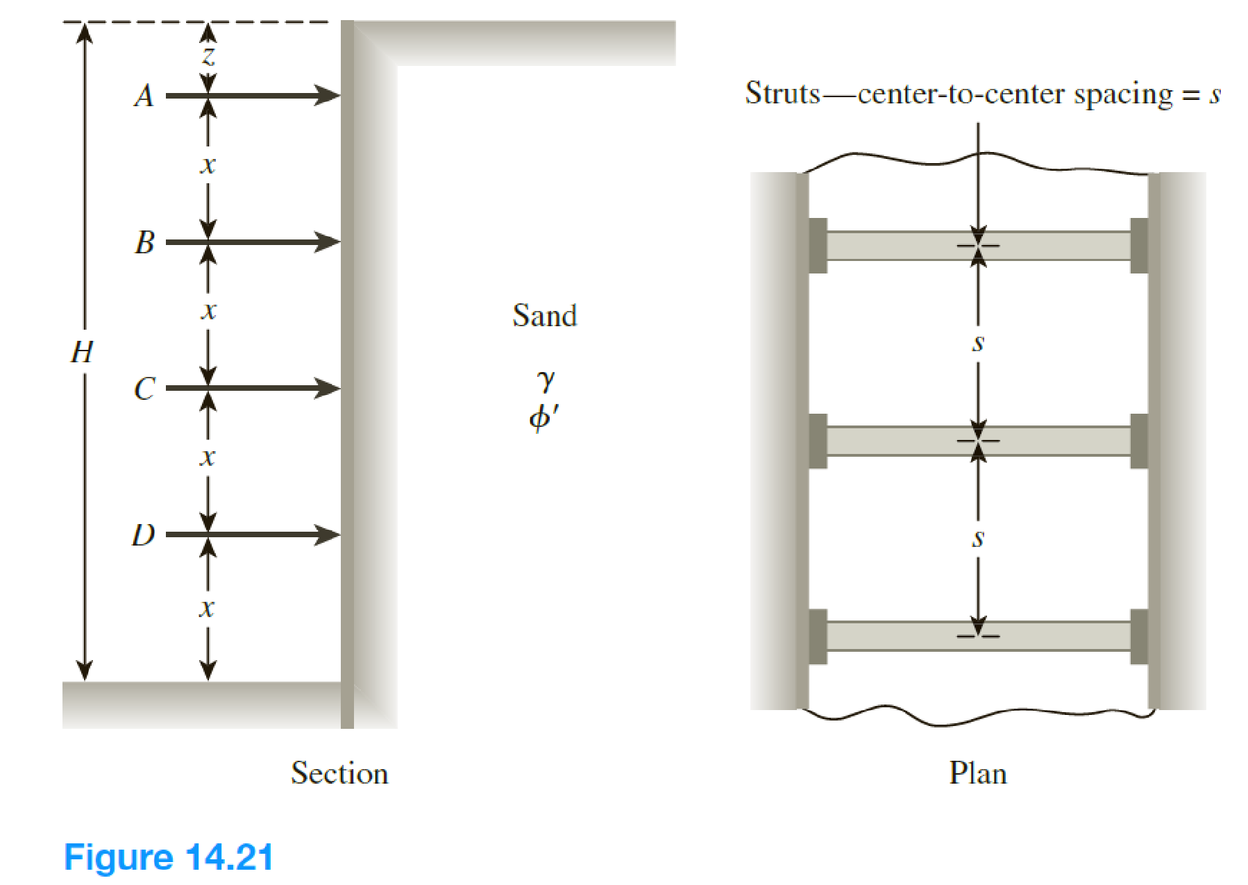
Chapter 14, Problem 14.14P
The elevation and plan of a bracing system for an open cut in sand are shown in Figure 14.21. Using Peck’s empirical pressure diagrams, determine the design strut loads. Given: γsand = 18 kN/m3, ϕ' = 38°, x = 3 m, z = 1.25 m, and s = 3 m.
Expert Solution & Answer

Trending nowThis is a popular solution!

Students have asked these similar questions
It is required to design a cantilever retaining wall to retain a 5.0 m high sandy backfill. The dimensions of the cantilever wall are shown in Figure 15.52 along with the soil properties. Check the stability with respect to sliding and overturning, based on the active earth pressures determined, usinga. Coulomb's earth pressure theory (δ' = 24°), andb. Rankine's earth pressure theory.The unit weight of concrete is 24 .0 kN/m3
The section of masonry dam is shown in Fig. U. If the uplift pressure variesuniformly from full hydrostatic at the heel to full hydrostatic at the toe, but acts only 2/3 of the area of the base,
find: (a) the location of the resultant, (b) factor safety against overturning, (c) factor of safety against sliding if the coefficient of friction between base and foundation is 0.60.
In the figure shown, the concrete dam is 16m high and 13m wide at the base. If the specific weight of the concrete is 23.544KN/m^3 and height of water in the upstream side is 15m, find the factor of safety against sliding, factor of safety against overturning, and the unit pressure on the foundation. Assume there is a hydrostatic uplift that varies uniformly from full hydrostatic head at the heel of the dam to zero at the toe and that the coefficient of friction between the dam and the foundation is 0.50.
Chapter 14 Solutions
Principles of Geotechnical Engineering (MindTap Course List)
Knowledge Booster


Learn more about
Need a deep-dive on the concept behind this application? Look no further. Learn more about this topic, civil-engineering and related others by exploring similar questions and additional content below.Similar questions
- The cross section of a braced cut supporting a sheet pile installation in a clay soil is shown in Figure 14.22. Given: H = 12 m, clay = 17.9 kN/m3, = 0, c = 75 kN/m2, and the center-to-center spacing of struts in plan view, s = 3 m. a. Using Pecks empirical pressure diagrams, draw the earth-pressure envelope. b. Determine the strut loads at levels A, B, and C.arrow_forwardDetermine the factor of safety against bottom heave for the braced cut described in Problem 15.18. Use Eqs. (15.66) and (15.70). For Eq. (15.70), assume the length of the cut, L = 18 m. 15.18 Refer to Figure 15.51 in which = 17.5 kN/m3, c = 60 kN/m2, and center-to-center spacing of struts is 5 m. Draw the earth pressure envelope and determine the strut loads at levels A, B, and C. FIG. 15.51arrow_forwardA braced cut shown in Figure P19.3 is to be made to a depth of 9.0 m in a saturated clay deposit where the unit weight is 17.65 kN/m3 and the undrained shear strength is 30 kN/m2. The struts are spaced horizontally at 3.0 m center to center. Find the strut loads.arrow_forward
- A retaining wall 6 m high supports cohesionless soil having a dry density of 1600 kg/m³, angle of resistance 32 and void ratio of 0.68. The surface of the soil is horizontal and level with the top of the wall. Neglecting wall friction and using Rankine’s formula for active pressure of a cohesionless soil. 1. Determine the nearest value of the total earth thrust on the wall in KN per lineal meter if the soil is dry. a. 73.1 b. 86.7 c. 62.4 d. 98.1 2. Find the nearest value of the thrust on the wall in KN per lineal meter if owing to inadequate drainage, it is waterlogged to a level of 3.5 m below the surface. a. 112 b. 171 c. 147 d. 153 3. Find at what height above the base of the wall the thrust acts during the waterlogged condition. a. 2.21 m b. 2.00 m c. 1.74 m d. 1.42 marrow_forwardA retaining wall 9 m high supports a cohesionless sandy soil with its face vertical as shown in figure below. Find active earth pressure on the wall , Take Yw = 9.81kN / (m ^ 3)arrow_forwardA retaining wall 8 m high supports a cohesionless soil having a dry density of 1600 kg/m^3, angle of shearing resistance is 33 degrees and void ratio of 0.68. The surface of the soil is horizontal and level with top of the wall. Neglect wall friction and use Rankine’s formula for active pressure of a cohesionless soil. Determine the value of earth thrust on the wall per meter length if the soil is dry. a. 121 kN b. 186 kN c. 148 kN d. 137 kN determine the value of earth thrust on the wall if water level is 3.5 m below the surface. a. 230 kN b. 250 kN c. 180 kN d. 210 kN find the height above the base of the wall where the thrust acts during the water logged condition. a. 3.50 m b. 2.67 m c. 1.75 m d. 2.25 marrow_forward
- Q.8 The depths of soil behind and in front of a rigid retaining wall are 25 ft and 10 ft. respectively, both the soil surfaces being horizontal (Fig. 3). The shear strength parameters for the soil are c = 600 lb/ft2, and Ø = 22°, and the unit weight is 110 lb/ft3. Using Rankine theory, determine the total active thrust behind the wall and the total passive resistance in front of the wall. Assume the water table is at a great deptharrow_forwardA damn having a triangular section has a vertical face 24 m high and base 12 m wide. Use sg=2.4 a. determine the height of water that could rise on the vertical side of the dam so that the maximum intensity of pressure at the toe is twice the average pressure at the base. Neglect hydrostatic uplift. b. What is the shearing stress at the base?arrow_forwardA braced wall is shown in Figure 14.20. Given: H = 7 m, naH = 2.8 m, =30, =20, = 18 kN/m3, and c = 0. Determine the active thrust, Pa, on the wall using the general wedge theory. Figure 14.20arrow_forward
- Refer to the braced cut shown in Figure P15.1. Given: γ = 17 kN/m3, Φ' = 35º, and c' = 0. The struts are located at 3 m center-to-center in the plan. Draw the earth-pressure envelope and determine the strut loads at levels A, B, and C.arrow_forwardFor the retaining wall shown in the figure, compute the factors of safety against overturning and sliding (analyze the latter both with and without passive earth pressure at the toe). Also determine the soil pressure at the base of the wall. Use the Rankine equation to compute passive earth pressure.arrow_forward
arrow_back_ios
arrow_forward_ios
Recommended textbooks for you
 Principles of Geotechnical Engineering (MindTap C...Civil EngineeringISBN:9781305970939Author:Braja M. Das, Khaled SobhanPublisher:Cengage Learning
 Principles of Foundation Engineering (MindTap Cou...Civil EngineeringISBN:9781305081550Author:Braja M. DasPublisher:Cengage Learning
 Fundamentals of Geotechnical Engineering (MindTap...Civil EngineeringISBN:9781305635180Author:Braja M. Das, Nagaratnam SivakuganPublisher:Cengage Learning
 Principles of Foundation Engineering (MindTap Cou...Civil EngineeringISBN:9781337705028Author:Braja M. Das, Nagaratnam SivakuganPublisher:Cengage Learning
Principles of Geotechnical Engineering (MindTap C...
Civil Engineering
ISBN:9781305970939
Author:Braja M. Das, Khaled Sobhan
Publisher:Cengage Learning
Principles of Foundation Engineering (MindTap Cou...
Civil Engineering
ISBN:9781305081550
Author:Braja M. Das
Publisher:Cengage Learning
Fundamentals of Geotechnical Engineering (MindTap...
Civil Engineering
ISBN:9781305635180
Author:Braja M. Das, Nagaratnam Sivakugan
Publisher:Cengage Learning
Principles of Foundation Engineering (MindTap Cou...
Civil Engineering
ISBN:9781337705028
Author:Braja M. Das, Nagaratnam Sivakugan
Publisher:Cengage Learning
How to build angle braces; Author: Country Living With The Harnish's;https://www.youtube.com/watch?v=3cKselS6rxY;License: Standard Youtube License