Electric Circuits. (11th Edition)
11th Edition
ISBN: 9780134746968
Author: James W. Nilsson, Susan Riedel
Publisher: PEARSON
bartleby

Concept explainers

bartleby

Videos

Question
Book Icon
Chapter 14, Problem 1P

(a)

To determine

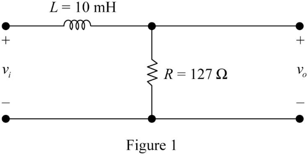
Find the value of the cutoff frequency in hertz for the RL filter shown in given figure.

(a)

Expert Solution
Check Mark

Answer to Problem 1P

The value of the cutoff frequency (fc) in hertz for the RL filter shown in given figure is 2021.27Hz.

Explanation of Solution

Given data:

Refer to given figure in the textbook.

Formula used:

Write the expression to calculate the angular cutoff frequency.

ωc=2πfc        (1)

Here,

fc is the value of cutoff frequency.

Write the expression to calculate the cutoff frequency of the RL low-pass filter.

ωc=RL        (2)

Here,

R is the value of the resistor , and

L is the value of the inductor.

Calculation:

The given filter circuit is drawn as Figure 1.

Electric Circuits. (11th Edition), Chapter 14, Problem 1P , additional homework tip  1

Substitute 127Ω for R and 10mH for L in equation (2) to find ωc.

ωc=127Ω10mH=127Ω10×103H {1m=103}=127Ω10×103Ωs {1H=1Ω1s}=12.7×10³rads

Simplify the above equation to find ωc.

ωc=12.7krads {1k=103}

Substitute 12.7×10³rads for ωc in equation (1).

(12.7×10³rads)=2πfc

Rearrange the above equation to find fc.

fc=(12.7×10³rads)2π=2021.271s=2021.27Hz {1Hz=11s}

Conclusion:

Thus, the value of the cutoff frequency (fc) in hertz for the RL filter shown in given figure is 2021.27Hz.

(b)

To determine

Find the value of the transfer function H(jω) at ωc, 0.2ωc and 5ωc.

(b)

Expert Solution
Check Mark

Answer to Problem 1P

The value of the transfer function H(jω) at ωc, 0.2ωc and 5ωc is 0.70745°, 0.98111.31° and 0.19678.69° respectively.

Explanation of Solution

Formula used:

Write the expression to calculate the impedance of the passive elements resistor and inductor.

ZR=R        (3)

ZL=jωL        (4)

Calculation:

The impedance circuit of the Figure 1 is drawn as Figure 2 using the equations (3) and (4).

Electric Circuits. (11th Edition), Chapter 14, Problem 1P , additional homework tip  2

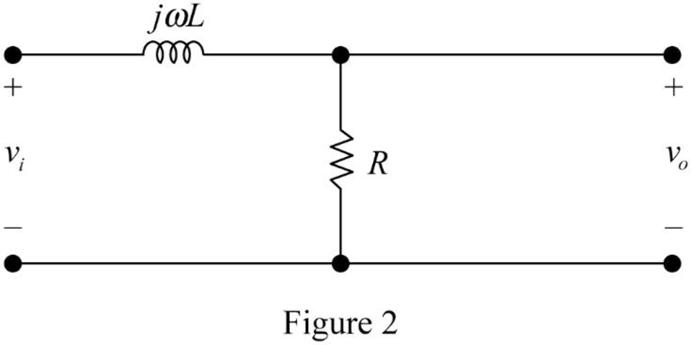
Apply voltage division rule on Figure 2 to find vo.

vo=RR+jωLvi

Rearrange the above equation to find vovi.

vovi=RR+jωL=RR(1+jωLR)=1(1+jω(RL))

Substitute the equation (2) in above equation to find vovi.

vovi=11+jωωc=1(ωc+jωωc)=ωcωc+jω

Write the expression to calculate the transfer function of the circuit in Figure 2.

H(jω)=vovi

Substitute ωcωc+jω for vovi in above equation to find H(jω).

H(jω)=ωcωc+jω

Substitute 12.7×10³rads for ωc in above equation to find H(jω).

H(jω)=(12.7×10³)(12.7×10³)+jω

H(jω)=1270012700+jω        (5)

Substitute ωc for ω in equation (5) to find H(jωc).

H(jωc)=1270012700+jωc

Substitute 12.7×10³rads for ωc in above equation to find H(jωc).

H(jωc)=1270012700+j(12.7×10³)=1270012700+j12700=0.70745°

Substitute 0.2ωc for ω in equation (5) to find H(j0.2ωc).

H(j0.2ωc)=1270012700+j(0.2ωc)

Substitute 12.7×10³rads for ωc in above equation to find H(j0.2ωc).

H(j0.2ωc)=1270012700+j(0.2(12.7×10³))=1270012700+j2540=0.98111.31°

Substitute 5ωc for ω in equation (5) to find H(j5ωc).

H(j5ωc)=1270012700+j(5ωc)

Substitute 12.7×10³rads for ωc in above equation to find H(j5ωc).

H(j5ωc)=1270012700+j(5(12.7×10³))=1270012700+j63500=0.19678.69°

Conclusion:

Thus, the value of the transfer function H(jω) at ωc, 0.2ωc and 5ωc is 0.70745°, 0.98111.31° and 0.19678.69° respectively.

(c)

To determine

Find the steady state expression for the output voltage (vo) when ω=ωc, ω=0.2ωc and ω=5ωc.

(c)

Expert Solution
Check Mark

Answer to Problem 1P

The steady state expression for the output voltage (vo) when ω=ωc, ω=0.2ωc and ω=5ωc is 7.07cos(1270045°)V, 9.81cos(2540t11.31°)V and 1.96cos(63500t78.69°)V respectively.

Explanation of Solution

Given data:

The input voltage is,

vi=10cosωtV

Calculation:

From part (b),

vovi=ωcωc+jω

Rearrange the above equation to find vo.

vo=vi(ωcωc+jω)

Substitute 10cosωtV for vi and 12.7×10³rads for ωc in above equation to find vo.

vo=(10cosωt)((12.7×10³)(12.7×10³)+jω)

vo=(10cosωt)(1270012700+jω)        (6)

Substitute ωc for ω in equation (6) to find vo(t)|ωc.

vo(t)|ωc=(10cosωct)(1270012700+jωc)

Substitute 12.7×10³rads for ωc in above equation to find vo(t)|ωc.

vo(t)|ωc=(10cos(12.7×10³)t)(1270012700+j(12.7×10³))V=(10cos(12.7×10³t)+0°)(0.70745°)V=(100°)(0.70745°)V {Acos(ωt+ϕ)=Aϕ}=(7.0745°)V

Simplify the above equation to find vo(t)|ωc.

vo(t)|ωc=7.07cos(ωt45°)V {Aϕ=Acos(ωt+ϕ)}=7.07cos(ωct45°)V {ω=ωc}=7.07cos((12.7×10³)t45°)V=7.07cos(12700t45°)V

Substitute 0.2ωc for ω in equation (6) to find vo(t)|0.2ωc.

vo(t)|0.2ωc=(10cos(0.2ωc)t)(1270012700+j(0.2ωc))

Substitute 12.7×10³rads for ωc in above equation to find vo(t)|0.2ωc.

vo(t)|0.2ωc=(10cos(0.2)(12.7×10³)t)(1270012700+j(0.2)(12.7×10³))V=(10cos((2.54×10³t)+0°))(0.98111.31°)V=(100°)(0.98111.31°)V {Acos(ωt+ϕ)=Aϕ}=(9.8111.31°)V

Simplify the above equation to find vo(t)|0.2ωc.

vo(t)|0.2ωc=9.81cos(ωt11.31°)V {Aϕ=Acos(ωt+ϕ)}=9.81cos(0.2ωct11.31°)V {ω=0.2ωc}=9.81cos(0.2(12.7×10³)t11.31°)V=9.81cos(2540t11.31°)V

Substitute 5ωc for ω in equation (6) to find vo(t)|5ωc.

vo(t)|5ωc=(10cos(5ωc)t)(1270012700+j(5ωc))

Substitute 12.7×10³rads for ωc in above equation to find vo(t)|5ωc.

vo(t)|5ωc=(10cos(5)(12.7×10³)t)(1270012700+j(5)(12.7×10³))V=(10cos(63500t+0°))(0.19678.69°)V=(100°)(0.19678.69°)V {Acos(ωt+ϕ)=Aϕ}=(1.9678.69°)V

Simplify the above equation to find vo(t)|5ωc.

vo(t)|5ωc=1.96cos(ωt78.69°)V {Aϕ=Acos(ωt+ϕ)}=1.96cos(5ωct78.69°)V {ω=5ωc}=1.96cos(5(12.7×10³)t78.69°)V=1.96cos(63500t78.69°)V

Conclusion:

Thus, the steady state expression for the output voltage (vo) when ω=ωc, ω=0.2ωc and ω=5ωc is 7.07cos(1270045°)V, 9.81cos(2540t11.31°)V and 1.96cos(63500t78.69°)V respectively.

Want to see more full solutions like this?

Subscribe now to access step-by-step solutions to millions of textbook problems written by subject matter experts!

Chapter 14 Solutions

Electric Circuits. (11th Edition)

Ch. 14.5 - Prob. 11APCh. 14 - Prob. 1PCh. 14 - Consider the low-pass filter in Fig. P14.2, which...Ch. 14 - Use a 5 mH inductor to design a low-pass, RL....Ch. 14 - A resistor, denoted as Rl, is added in series with...Ch. 14 - Use a 250 Ω resistor to design a low-pass passive...Ch. 14 - Consider the low-pass filler designed in Problem...Ch. 14 - Find the cutoff frequency (in hertz) of the...Ch. 14 - Prob. 8PCh. 14 - Use a 500 nF capacitor to design a low-pass...Ch. 14 - Prob. 10PCh. 14 - Consider the circuit shown in Fig. P14.11. What is...Ch. 14 - Prob. 12PCh. 14 - Prob. 13PCh. 14 - Prob. 14PCh. 14 - Prob. 15PCh. 14 - Prob. 16PCh. 14 - Prob. 17PCh. 14 - Prob. 18PCh. 14 - Prob. 19PCh. 14 - Prob. 20PCh. 14 - Prob. 21PCh. 14 - Prob. 22PCh. 14 - Prob. 23PCh. 14 - Prob. 24PCh. 14 - Prob. 25PCh. 14 - Using a 50 nF capacitor in the bandpass circuit...Ch. 14 - Design a series RLC bandpass filter using only...Ch. 14 - Prob. 28PCh. 14 - Design a series RLC bandpass filter using only...Ch. 14 - Prob. 30PCh. 14 - Consider the circuit shown in Fig. P14.31. Find...Ch. 14 - Prob. 32PCh. 14 - The purpose of this problem is to investigate how...Ch. 14 - The parameters in the circuit in Fig. P14.33 are R...Ch. 14 - Prob. 35PCh. 14 - Prob. 36PCh. 14 - Prob. 37PCh. 14 - Prob. 38PCh. 14 - Prob. 39PCh. 14 - Prob. 40PCh. 14 - Prob. 41PCh. 14 - Use a 500 nF capacitor to design a bandreject...Ch. 14 - Prob. 43PCh. 14 - Prob. 44PCh. 14 - Prob. 45PCh. 14 - The parameters in the circuit in Fig. P14.45 are R...Ch. 14 - Prob. 47PCh. 14 - Consider the series RLC circuit shown in Fig....Ch. 14 - Repeat Problem 14.49 for the circuit shown in Fig....Ch. 14 - Prob. 51PCh. 14 - Design a DTMF high-band bandpass filter similar to...Ch. 14 - Prob. 53P
Knowledge Booster
Background pattern image
Electrical Engineering
Learn more about
Need a deep-dive on the concept behind this application? Look no further. Learn more about this topic, electrical-engineering and related others by exploring similar questions and additional content below.
Recommended textbooks for you
Text book image
Introductory Circuit Analysis (13th Edition)
Electrical Engineering
ISBN:9780133923605
Author:Robert L. Boylestad
Publisher:PEARSON
Text book image
Delmar's Standard Textbook Of Electricity
Electrical Engineering
ISBN:9781337900348
Author:Stephen L. Herman
Publisher:Cengage Learning
Text book image
Programmable Logic Controllers
Electrical Engineering
ISBN:9780073373843
Author:Frank D. Petruzella
Publisher:McGraw-Hill Education
Text book image
Fundamentals of Electric Circuits
Electrical Engineering
ISBN:9780078028229
Author:Charles K Alexander, Matthew Sadiku
Publisher:McGraw-Hill Education
Text book image
Electric Circuits. (11th Edition)
Electrical Engineering
ISBN:9780134746968
Author:James W. Nilsson, Susan Riedel
Publisher:PEARSON
Text book image
Engineering Electromagnetics
Electrical Engineering
ISBN:9780078028151
Author:Hayt, William H. (william Hart), Jr, BUCK, John A.
Publisher:Mcgraw-hill Education,
What is Filter & Classification of Filters | Four Types of Filters | Electronic Devices & Circuits; Author: SimplyInfo;https://www.youtube.com/watch?v=9x1Sjz-VPSg;License: Standard Youtube License