
Concept explainers
Videos
For the pump and piping system of Prob. 14-35E, plot the required pump head
The plot between the available head and the capacity of the pump.
Answer to Problem 36EP
The plot between the available head and the capacity of the pump is 
Explanation of Solution
Given information:
The shutoff head is
Write the expression for the required head using the energy balance equation.
Here, the initial pressure is
Write the expression for the roughness factor.
Here, the diameter of the pipe is
Write the expression for the minor losses.
Here, the minor loss coefficient at pipe entrance is
Write the expression for the frictional loss head.
Here, the friction factor is
Write the expression for the available head.
Here, the shutoff head is
Write the expression for the capacity.
Substitute
Write the expression for the Reynolds number.
Here, the density of the water is
Write the expression for the friction factor using the Colebrook equation.
Calculation:
Refer to table A-3E Properties of saturated water to obtain the density of water as
Substitute
Substitute
Substitute
Substitute
Since, the required head is equal to the available head that is
Substitute
Substitute
Substitute
Substitute
Substitute
Substitute
The different values of the capacity and the available head is shown in the below Table.
| S.No. | Capacity | Available head |
| 1 | ||
| 2 | ||
| 3 | ||
| 4 |
Draw the plot between the available head and the capacity of the pump for different values along with the required head.
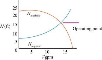
Figure-(1)
Conclusion:
The plot between the available head and the capacity of the pump is 
Want to see more full solutions like this?
Chapter 14 Solutions
Fluid Mechanics: Fundamentals and Applications


- A cylindrical tank is being filled with water flowing with constant velocity V1 through a tap (Tap 1) that has an opening of diameter D1. The tank is initially empty and contains a tap (Tap 2) placed H1 m above the bottom of the tank that drains waterat a velocity of ? = √2?h. Assuming flow through Tap 2 starts the moment Tank 1 2height reaches H1 m, write the differential equation governing the change of water level inside the tank with time (?h =? );??i) Before water level reaches H1.ii) After water level reaches H1 up until the tank is full.Do NOT attempt to solve the differential equations!Just drive the differential equations and write the boundaries of the definite integrals.arrow_forwardThis problem is useful for the preliminary design of a hydroturbine. From the material learned in this chapter, it is fairly simple to estimate how much power a hydroturbine can generate, given only the flow rate of water and the elevation difference upstream and downstream of the dam. A dam has a gross head of 15.5 m and a flow rate of 0.22 m3 /s. Approximating the overall efficiency of the turbine/generator to be 75%, estimate the electrical power (in kW) that couldbe produced.arrow_forwardWater is pumped between two reservoirs in a pipeline with the following characteristics; (d=275mm, L= 50m, = 0.02, minor loss is neglected. The pump performance curve is approximated by the equation: H,=21.5-6507 Where H, is in meters and Q is in m/s. Determine the discharge O and pump head /7 when two pumps in series are used for total static head (4Z=25m).arrow_forward
- For the conduction of the water there is a height difference of 38 m. The results obtained from the hydraulic calculation for three different diameters are shown in the following table Diameter, in. Total head loss, mca 8 56.5 12 37.2 16 29.1 What will be the available driving load? TRANSLATED FROM Para la conducción del agua se cuenta con un desnivel de cotas de 38 m. Los resultados obtenidos del cálculo hidráulico para tres diámetros diferentes son mostrados en la siguiente tabla: Diámetro, plgs. Pérdida de carga total, mca 8 56.5 12 37.2 16 29.1 ¿Cuál será la carga de conducción disponible?arrow_forwardThe head-discharge relationship for a certain pump can be represented by the equation H-29-6Q^2 The pump is fixed 2 m shove the water surface tank at a level 10 m above the pump. The suction and delivery pipes are 12 m and 720 m long, respectively and each pipe is 0.5 m in diameter. The Estimate the discharge (in m³/s) at the best operating point for the pumping system,arrow_forwardA wind turbine generator system having a diameter of 82.5 m produces 1.5 MW at a wind speed of 12 m/s. Determine the diameter of blade necessary to produce 10 MW of power assuming the efficiency is the same for both designs and p = 1.21 kg/m3 for air.arrow_forward
- The system consists of 1200 m of 5 cm cast iron pipe, two 45° and four 90° flanged long-radius elbows, a fully open flanged globe valve, and a sharp exit into a reservoir. If the elevation at point 1 is 400 m, what gage pressure is required at point 1 to deliver 0.005 m3/s of water into the reservoir? Use the following: v = 1 x 10⁻⁶ m2/s Kentrance = 0.5 Kexit = 1 Kvalve = 6.9 f = 0.0316 γ = 9810 N/m3 Choices: 3.44 Mpa 1.02 MPa 3.48 Mpa 1.00 MPa None of the choicesarrow_forwardWater is discharging through a circular orifice plate 25mm in diameter in the vertical side of the tank of a constant plan area 0.4m2. It is observed that the time taken for the water level to fall from 1.5m to 1.4m above the orifice is24.5 seconds. Show that the average volumetric flow rate is 1.633*10^-3 m^3/s.By approximating the height as being a constant value (1.4m, 1.5m or 1.45m) for discharge rate calculation, estimate the coefficient of discharge for this orifice plate, and give highest and lowest plausible values from the data supplied.arrow_forwardWrite the equation that defines actual (available) net positive suction head NPSH. From this definition, discuss at least five ways you can decrease the likelihood of cavitation in the pump, for the same liquid, temperature, and volume flow ratearrow_forward
- A surge chamber 10m in diameter is situated at the down stream end of a low pressure tunnel 9.8km long and 2.8m in diameter. At a steady discharge of 32m3/s the flow to the turbine is suddenly stopped by closure of the turbine inlet valves. Determine the maximum rise in level in the surge chamber.arrow_forwardWater travels through a circular pipe with a diameter of 400 mm and at a speed of 5 m/s. The inertial force created by the flow is: Question 2Answer a. 100000 kgs/m b. 10000 kgs/m c. 1000 kgs/m d. 1000000 kgs/marrow_forwardNeglecting head losses, determinewhat horsepower the pump must deliver toproduce the flow as shown. Here theelevations at points A, B, C, and D are 110 ft.200 ft, 110 ft and 90 ft, respectively. The nozzle area is 0.10 ft2arrow_forward
 Elements Of ElectromagneticsMechanical EngineeringISBN:9780190698614Author:Sadiku, Matthew N. O.Publisher:Oxford University Press
 Mechanics of Materials (10th Edition)Mechanical EngineeringISBN:9780134319650Author:Russell C. HibbelerPublisher:PEARSON
 Thermodynamics: An Engineering ApproachMechanical EngineeringISBN:9781259822674Author:Yunus A. Cengel Dr., Michael A. BolesPublisher:McGraw-Hill Education
 Control Systems EngineeringMechanical EngineeringISBN:9781118170519Author:Norman S. NisePublisher:WILEY
 Mechanics of Materials (MindTap Course List)Mechanical EngineeringISBN:9781337093347Author:Barry J. Goodno, James M. GerePublisher:Cengage Learning
 Engineering Mechanics: StaticsMechanical EngineeringISBN:9781118807330Author:James L. Meriam, L. G. Kraige, J. N. BoltonPublisher:WILEY