Fundamentals of Electric Circuits
6th Edition
ISBN: 9780078028229
Author: Charles K Alexander, Matthew Sadiku
Publisher: McGraw-Hill Education
bartleby

Videos

Textbook Question
Book Icon
Chapter 14, Problem 66P

A “general” first-order filter is shown in Fig. 14.93.

  1. (a) Show that the transfer function is

    H ( s ) = R 4 R 3 + R 4 × s + ( 1 / R 1 C ) [ R 1 / R 2 R 3 / R 4 ] s + 1 / R 2 C , s =

  2. (b) What condition must be satisfied for the circuit to operate as a high-pass filter?
  3. (c) What condition must be satisfied for the circuit to operate as a low-pass filter?
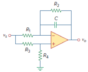
Chapter 14, Problem 66P, A general first-order filter is shown in Fig. 14.93. (a) Show that the transfer function is

Figure 14.93

(a)

Expert Solution
Check Mark
To determine

Prove that the transfer function H(s) for the circuit shown in Figure 14.93 is R4R3+R4×s+(1R1C)[R1R2R3R4]s+1R2C

Explanation of Solution

Given data:

Refer to Figure 14.93 in the textbook.

Formula used:

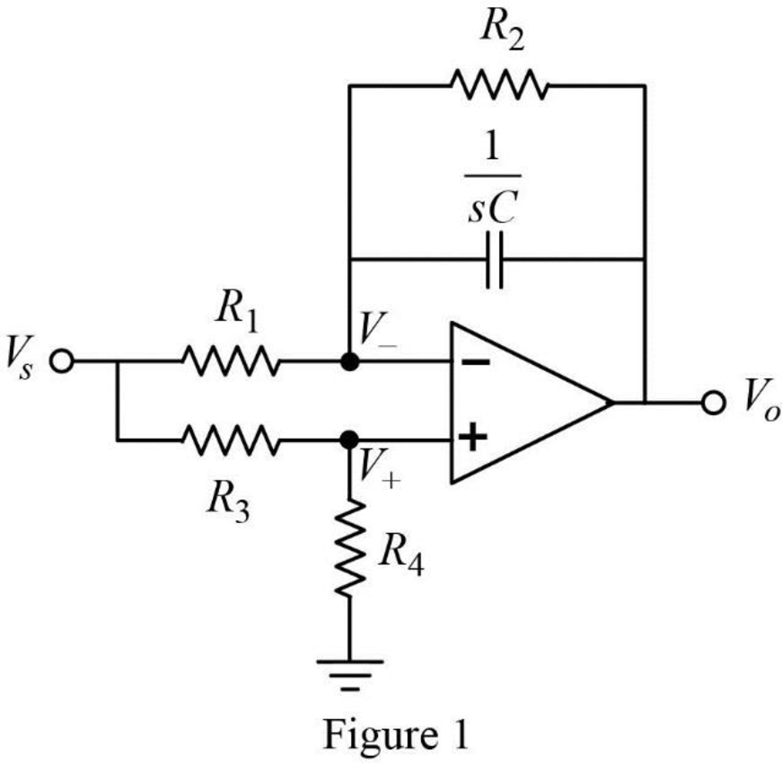
Write the general expression to calculate the transfer function of the circuit in Figure 1.

H(s)=VoVs        (1)

Here,

Vo is the output response of the system, and

Vs is the input response of the system.

Calculation:

The given circuit is redrawn as shown in Figure 1 in s-domain.

Fundamentals of Electric Circuits, Chapter 14, Problem 66P

Apply Kirchhoff’s current law at the node V+ in Figure 1.

V+VsR3+V+R4=0V+R3VsR3+V+R4=0(1R3+1R4)V+=VsR3

Rearrange the equation to find V+.

V+=VsR3(1R3+1R4)

V+=Vs(1+R3R4)        (2)

Apply Kirchhoff’s current law at the node V in Figure 1.

VVsR1+VVo(1sC)+VVoR2=0VR1VsR1+sCVsCVo+VR2VoR2=0

(1R1+1R2+sC)VVsR1(sC+1R2)Vo=0        (3)

Since, for an ideal operational amplifier, V+=V. Therefore

Substitute V for V+ in equation (2).

V=Vs(1+R3R4)        (4)

Substitute equation (4) in equation (3).

(1R1+1R2+sC)(Vs(1+R3R4))VsR1(sC+1R2)Vo=0(Vs(1R1+1R2+sC)(1+R3R4))VsR1=(sC+1R2)Vo(1R1+1R2+sC(1+R3R4)1R1)Vs=(sC+1R2)Vo

Rearrange the equation as follows,

VoVs=(1R1+1R2+sC)(1+R3R4)(1R1)sC+1R2=(1R1+1R2+sC)(1R1)(1+R3R4)(sC+1R2)(1+R3R4)=1R1+1R2+sC1R1R3R1R4(sC+1R2)(1+R3R4)=(R4R3+R4)×1R2+sCR3R1R4(sC+1R2)

Reduce the equation as follows,

VoVs=(R4R3+R4)×1CR2+sR3CR1R4(s+1R2C)=(R4R3+R4)×s+1R1C(R1R2R3R4)(s+1R2C)

Substitute (R4R3+R4)×s+1R1C(R1R2R3R4)(s+1R2C) for VoVs in equation (1) to find the transfer function H(s).

H(s)=(R4R3+R4)×s+1R1C(R1R2R3R4)(s+1R2C)

Conclusion:

Thus, the transfer function H(s) for the given circuit shown in Figure 14.92 is (1+RfRi)(jωRC1+jωRC) and is proved.

(b)

Expert Solution
Check Mark
To determine

Examine the condition to be satisfied to operate as a high-pass filter of the given circuit.

Explanation of Solution

Given data:

Refer to Part (a),

H(s)=(R4R3+R4)×s+1R1C(R1R2R3R4)(s+1R2C)        (5)

Calculation:

For high-pass filter, apply the limits s0 in equation (5). That is,

(R4R3+R4)×0+1R1C(R1R2R3R4)(0+1R2C)=01R1C(R1R2R3R4)=0R1R2R3R4=0

R1R2=R3R4        (6)

Substitute equation (6) in equation (5) to find the transfer function for high-pass filter H(s).

H(s)=(R4R3+R4)×s+1R1C(R3R4R3R4)(s+1R2C)=(R4R3+R4)×s(s+1R2C)

Conclusion:

Thus, the condition to be satisfied to operate as a high-pass filter of the given circuit is at R1R2=R3R4.

(c)

Expert Solution
Check Mark
To determine

Examine the condition to be satisfied to operate as a low-pass filter of the given circuit.

Explanation of Solution

Reduce the equation (5) as follows,

H(s)=(R4R3+R4)×s[1+1sR1C(R1R2R3R4)]s(1+1sR2C)

H(s)=(R4R3+R4)×1+1sR1C(R1R2R3R4)1+1sR2C        (7)

For low-pass filter, apply the limits s in equation (7). That is,

(R4R3+R4)×1+1()R1C(R1R2R3R4)1+1()R2C=0R4R3+R4=0R4R3(1+R4R3)=0

R4R3=0        (8)

Therefore, if the resistance R3 tends to infinity only the equation (8) satisfies the condition to exist for low-pass filter. That is, R3.

Rearrange the equation (5) as follows,

H(s)=(R4R3(1+R4R3))×R3[sR3+1R1C(R1R3R21R4)](s+1R2C)

H(s)=(R4(1+R4R3))×[sR3+1R1C(R1R3R21R4)](s+1R2C)        (9)

Substitute for R3 to find the transfer function for low-pass filter H(s).

H(s)=(R4(1+R4))×[s+1R1C(R1()R21R4)](s+1R2C)=(R4)×[1R1C(1R4)](s+1R2C)=(1R1C)(s+1R2C)

Conclusion:

Thus, the condition to be satisfied to operate as a low-pass filter of the given circuit is at R3.

Want to see more full solutions like this?

Subscribe now to access step-by-step solutions to millions of textbook problems written by subject matter experts!
Students have asked these similar questions
Given a network with the following transfer function, G(s) = 800(s + 0.5)/ s(s + 100)(s + 2)2 Construct the Bode magnitude and phase plots for the network.
The open loop transfer function for a system is  G(s)H(s)=K(s+1)/s(s-1)(s^2 +4s+16) Using Bode Plott find the value of K that renders the system conditionally stable
An input, r(t), defined asr(t) = 0,  t < 0r(t) 3.0 t >0is applied to a system that can be described by a transfer function, T(p), whereT(p) = (24p + 208)/(p2+12p+52)Determine the system response, y(t), and sketch the output waveform.

Chapter 14 Solutions

Fundamentals of Electric Circuits

Ch. 14.7 - Design a band-pass filter of the form in Fig....Ch. 14.8 - Design a high-pass filter with a high-frequency...Ch. 14.8 - Design a notch filter based on Fig. 14.47 for 0 =...Ch. 14.9 - Prob. 14PPCh. 14.10 - Obtain the frequency response of the circuit in...Ch. 14.10 - Consider the network in Fig. 14.57. Use PSpice to...Ch. 14.12 - For an FM radio receiver, the incoming wave is in...Ch. 14.12 - Repeat Example 14.18 for band-pass filter BP6....Ch. 14.12 - If each speaker in Fig. 14.66 has an 8- resistance...Ch. 14 - Prob. 1RQCh. 14 - On the Bode magnitude plot, the slope of 1/5+j2...Ch. 14 - On the Bode phase plot for 0.5 50, the slope of...Ch. 14 - How much inductance is needed to resonate at 5 kHz...Ch. 14 - The difference between the half-power frequencies...Ch. 14 - Prob. 6RQCh. 14 - Prob. 7RQCh. 14 - Prob. 8RQCh. 14 - What kind of filter can be used to select a signal...Ch. 14 - A voltage source supplies a signal of constant...Ch. 14 - Find the transfer function Io/Ii of the RL circuit...Ch. 14 - Using Fig. 14.69, design a problem to help other...Ch. 14 - For the circuit shown in Fig. 14.70, find H(s) =...Ch. 14 - Find the transfer function H(s) = Vo/Vi of the...Ch. 14 - For the circuit shown in Fig. 14.72, find H(s) =...Ch. 14 - For the circuit shown in Fig. 14.73, find H(s) =...Ch. 14 - Calculate |H()| if HdB equals (a) 0.1 dB (b) 5 dB...Ch. 14 - Design a problem to help other students calculate...Ch. 14 - A ladder network has a voltage gain of...Ch. 14 - Design a problem to help other students better...Ch. 14 - Sketch the Bode plots for H()=0.2(10+j)j(2+j)Ch. 14 - A transfer function is given by...Ch. 14 - Construct the Bode plots for...Ch. 14 - Draw the Bode plots for H()=250(j+1)j(2+10j+25)Ch. 14 - Prob. 15PCh. 14 - Sketch Bode magnitude and phase plots for...Ch. 14 - Sketch the Bode plots for G(s)=s(s+2)2(s+1), s = jCh. 14 - A linear network has this transfer function...Ch. 14 - Sketch the asymptotic Bode plots of the magnitude...Ch. 14 - Design a more complex problem than given in Prob....Ch. 14 - Sketch the magnitude Bode plot for...Ch. 14 - Find the transfer function H() with the Bode...Ch. 14 - The Bode magnitude plot of H() is shown in Fig....Ch. 14 - The magnitude plot in Fig. 14.76 represents the...Ch. 14 - A series RLC network has R = 2 k, L = 40 mH, and C...Ch. 14 - Design a problem to help other students better...Ch. 14 - Design a series RLC resonant circuit with 0 = 40...Ch. 14 - Design a series RLC circuit with B = 20 rad/s and...Ch. 14 - Let vs = 20 cos(at) V in the circuit of Fig....Ch. 14 - A circuit consisting of a coil with inductance 10...Ch. 14 - Design a parallel resonant RLC circuit with 0 =...Ch. 14 - Design a problem to help other students better...Ch. 14 - A parallel resonant circuit with a bandwidth of 40...Ch. 14 - A parallel RLC circuit has R = 100 k, L = 100 mH,...Ch. 14 - A parallel RLC circuit has R = 10 k, L = 100 mH,...Ch. 14 - It is expected that a parallel RLC resonant...Ch. 14 - Rework Prob. 14.25 if the elements are connected...Ch. 14 - Find the resonant frequency of the circuit in Fig....Ch. 14 - For the tank circuit in Fig. 14.79, find the...Ch. 14 - Prob. 40PCh. 14 - Using Fig. 14.80, design a problem to help other...Ch. 14 - For the circuits in Fig. 14.81, find the resonant...Ch. 14 - Calculate the resonant frequency of each of the...Ch. 14 - For the circuit in Fig. 14.83, find: (a) the...Ch. 14 - For the circuit shown in Fig. 14.84. find 0, B,...Ch. 14 - For the network illustrated in Fig. 14.85, find...Ch. 14 - Prob. 47PCh. 14 - Find the transfer function Vo/Vs of the circuit in...Ch. 14 - Design a problem to help other students better...Ch. 14 - Determine what type of filter is in Fig. 14.87....Ch. 14 - Design an RL low-pass filter that uses a 40-mH...Ch. 14 - Design a problem to help other students better...Ch. 14 - Design a series RLC type band-pass filter with...Ch. 14 - Design a passive band-stop filter with 0 = 10...Ch. 14 - Determine the range of frequencies that will be...Ch. 14 - (a) Show that for a band-pass filter,...Ch. 14 - Determine the center frequency and bandwidth of...Ch. 14 - The circuit parameters for a series RLC band-stop...Ch. 14 - Find the bandwidth and center frequency of the...Ch. 14 - Obtain the transfer function of a high-pass filter...Ch. 14 - Find the transfer function for each of the active...Ch. 14 - The filter in Fig. 14.90(b) has a 3-dB cutoff...Ch. 14 - Design an active first-order high-pass filter with...Ch. 14 - Obtain the transfer function of the active filter...Ch. 14 - A high-pass filter is shown in Fig. 14.92. Show...Ch. 14 - A general first-order filter is shown in Fig....Ch. 14 - Design an active low-pass filter with dc gain of...Ch. 14 - Design a problem to help other students better...Ch. 14 - Design the filter in Fig. 14.94 to meet the...Ch. 14 - A second-order active filter known as a...Ch. 14 - Use magnitude and frequency scaling on the circuit...Ch. 14 - Design a problem to help other students better...Ch. 14 - Calculate the values of R, L, and C that will...Ch. 14 - Prob. 74PCh. 14 - In an RLC circuit, R = 20 , L = 4 H, and C = 1 F....Ch. 14 - Given a parallel RLC circuit with R = 5 k, L = 10...Ch. 14 - A series RLC circuit has R = 10 , 0 = 40 rad/s,...Ch. 14 - Redesign the circuit in Fig. 14.85 so that all...Ch. 14 - Refer to the network in Fig. 14.96. (a) Find...Ch. 14 - (a) For the circuit in Fig. 14.97, draw the new...Ch. 14 - The circuit shown in Fig. 14.98 has the impedance...Ch. 14 - Scale the low-pass active filter in Fig. 14.99 so...Ch. 14 - The op amp circuit in Fig. 14.100 is to be...Ch. 14 - Using PSpice or MultiSim, obtain the frequency...Ch. 14 - Use PSpice or MultiSim to obtain the magnitude and...Ch. 14 - Using Fig. 14.103, design a problem to help other...Ch. 14 - In the interval 0.1 f 100 Hz, plot the response...Ch. 14 - Use PSpice or MultiSim to generate the magnitude...Ch. 14 - Obtain the magnitude plot of the response Vo in...Ch. 14 - Obtain the frequency response of the circuit in...Ch. 14 - For the tank circuit of Fig. 14.79, obtain the...Ch. 14 - Using PSpice or MultiSim, plot the magnitude of...Ch. 14 - For the phase shifter circuit shown in Fig....Ch. 14 - For an emergency situation, an engineer needs to...Ch. 14 - A series-tuned antenna circuit consists of a...Ch. 14 - The crossover circuit in Fig. 14.108 is a low-pass...Ch. 14 - The crossover circuit in Fig. 14.109 is a...Ch. 14 - A certain electronic test circuit produced a...Ch. 14 - In an electronic device, a series circuit is...Ch. 14 - In a certain application, a simple RC low-pass...Ch. 14 - In an amplifier circuit, a simple RC high-pass...Ch. 14 - Practical RC filter design should allow for source...Ch. 14 - The RC circuit in Fig. 14.111 is used for a lead...Ch. 14 - A low-quality-factor, double-tuned band-pass...
Knowledge Booster
Background pattern image
Electrical Engineering
Learn more about
Need a deep-dive on the concept behind this application? Look no further. Learn more about this topic, electrical-engineering and related others by exploring similar questions and additional content below.
Similar questions
SEE MORE QUESTIONS
Recommended textbooks for you
Text book image
Introductory Circuit Analysis (13th Edition)
Electrical Engineering
ISBN:9780133923605
Author:Robert L. Boylestad
Publisher:PEARSON
Text book image
Delmar's Standard Textbook Of Electricity
Electrical Engineering
ISBN:9781337900348
Author:Stephen L. Herman
Publisher:Cengage Learning
Text book image
Programmable Logic Controllers
Electrical Engineering
ISBN:9780073373843
Author:Frank D. Petruzella
Publisher:McGraw-Hill Education
Text book image
Fundamentals of Electric Circuits
Electrical Engineering
ISBN:9780078028229
Author:Charles K Alexander, Matthew Sadiku
Publisher:McGraw-Hill Education
Text book image
Electric Circuits. (11th Edition)
Electrical Engineering
ISBN:9780134746968
Author:James W. Nilsson, Susan Riedel
Publisher:PEARSON
Text book image
Engineering Electromagnetics
Electrical Engineering
ISBN:9780078028151
Author:Hayt, William H. (william Hart), Jr, BUCK, John A.
Publisher:Mcgraw-hill Education,
Systems and Simulation - Lecture 3: Modelling of Mechanical systems; Author: bioMechatronics Lab;https://www.youtube.com/watch?v=fMcDdyoC9mA;License: Standard Youtube License