Fundamentals of Electric Circuits
6th Edition
ISBN: 9780078028229
Author: Charles K Alexander, Matthew Sadiku
Publisher: McGraw-Hill Education
bartleby

Videos

Textbook Question
Book Icon
Chapter 14, Problem 96P

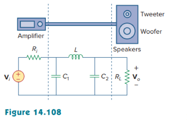
The crossover circuit in Fig. 14.108 is a low-pass filter that is connected to a woofer. Find the transfer function H(ω) = Vo(ω)/Vi(ω).

Chapter 14, Problem 96P, The crossover circuit in Fig. 14.108 is a low-pass filter that is connected to a woofer. Find the

Expert Solution & Answer
Check Mark
To determine

Find the transfer function H(ω)=Vo(ω)Vi(ω) of the crossover circuit shown in Figure 14.108.

Answer to Problem 96P

The transfer function H(ω) of the crossover circuit shown in Figure 14.108 is RL(RL+Riω2(RLLC2+RiLC1)+j(ω(L+RiRLC2+RiRLC1)ω3(RiRLLC1C2))).

Explanation of Solution

Given data:

Refer to Figure 14.108 in the textbook.

Formula used:

Write a general expression to calculate the impedance of resistor in s-domain.

ZR=R (1)

Here,

R is the value of the resistor.

Write a general expression to calculate the impedance of an inductor in s-domain.

ZL=sL (2)

Here,

L is the value of the inductor.

Write a general expression to calculate the impedance of a capacitor in s-domain.

ZC=1sC (3)

Here,

C is the value of the capacitor.

Write the general expression to calculate the transfer function of the system

H(ω)=Vo(ω)Vi(ω) (4)

Here,

Vo(ω) is the output response of the system, and

Vi(ω) is the input response of the system.

Calculation:

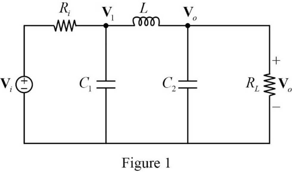
The given circuit is redrawn as Figure 1.

Fundamentals of Electric Circuits, Chapter 14, Problem 96P , additional homework tip  1

The s-domain circuit of the Figure 1 is drawn as Figure 2 using the equations (1), (2), and (3).

Fundamentals of Electric Circuits, Chapter 14, Problem 96P , additional homework tip  2

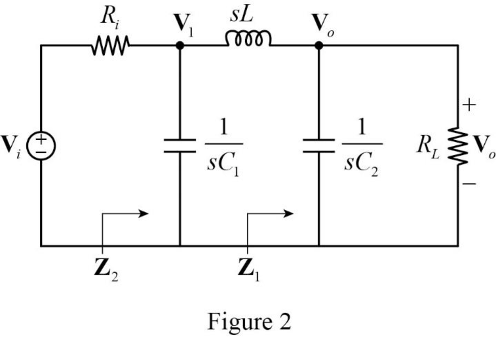
Refer to Figure 2, the resistor RL and the capacitor C2 is connected in parallel form. Therefore, the impedance Z1 is expressed as,

Z1=RL1sC2=(RL×1sC2)(RL+1sC2)=(RLsC2)(1+sRLC2sC2)=RL1+sRLC2

The Figure 2 is redrawn as Figure 3.

Fundamentals of Electric Circuits, Chapter 14, Problem 96P , additional homework tip  3

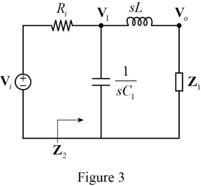
Refer to Figure 3, the inductor L and impedance Z1 is connected in series form and the combination is connected in parallel with the capacitor C1. Therefore, the impedance Z2 is expressed as,

Z2=1sC1(sL+Z1)

Substitute RL1+sRLC2 for Z1 in above equation to find Z2.

Z2=1sC1(sL+RL1+sRLC2)=1sC1(sL+s2RLLC2+RL1+sRLC2)=1sC1×(sL+s2RLLC2+RL1+sRLC2)1sC1+(sL+s2RLLC2+RL1+sRLC2)=(sL+s2RLLC2+RLsC1(1+sRLC2))(1+sRLC2+s2LC1+s3RLLC1C2+sRLC1sC1(1+sRLC2))

Simplify the above equation to find Z2.

Z2=sL+RL+s2RLLC21+sRLC2+s2LC1+sRLC1+s3RLLC1C2

The Figure 3 is redrawn as Figure 4.

Fundamentals of Electric Circuits, Chapter 14, Problem 96P , additional homework tip  4

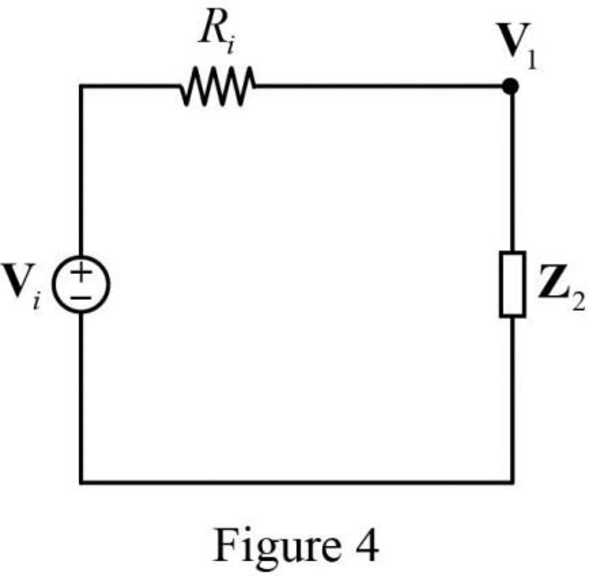
Apply voltage division rule on Figure 4 to find V1.

V1=Z2Z2+RiVi

Apply voltage division rule on Figure 3 to find Vo.

Vo=Z1Z1+sLV1

Substitute Z2Z2+RiVi for V1 in above equation to find Vo.

Vo=Z1Z1+sL(Z2Z2+RiVi)

Rearrange the above equation to find VoVi.

VoVi=(Z1Z1+sL)(Z2Z2+Ri)

Substitute RL1+sRLC2 for Z1 and sL+RL+s2RLLC21+sRLC2+s2LC1+sRLC1+s3RLLC1C2 for Z2 in above equation to find VoVi.

VoVi=((RL1+sRLC2)(RL1+sRLC2)+sL)((sL+RL+s2RLLC21+sRLC2+s2LC1+sRLC1+s3RLLC1C2)(sL+RL+s2RLLC21+sRLC2+s2LC1+sRLC1+s3RLLC1C2)+Ri)=(((RL1+sRLC2)(RL+sL+s2RLLC21+sRLC2))×((sL+RL+s2RLLC21+sRLC2+s2LC1+sRLC1+s3RLLC1C2)(sL+RL+s2RLLC2+Ri+sRiRLC2+s2RiLC1+sRiRLC1+s3RiRLLC1C21+sRLC2+s2LC1+sRLC1+s3RLLC1C2)))=((RLRL+sL+s2RLLC2)×(sL+RL+s2RLLC2s3(RiRLLC1C2)+s2(RLLC2+RiLC1)+s(L+RiRLC2+RiRLC1)+RL+Ri))=RL(s2RLLC2+sL+RL)((s2RLLC2+sL+RL)(s3(RiRLLC1C2)+s2(RLLC2+RiLC1)+s(L+RiRLC2+RiRLC1)+RL+Ri))

Simplify the above equation to find VoVi.

VoVi=RLs3(RiRLLC1C2)+s2(RLLC2+RiLC1)+s(L+RiRLC2+RiRLC1)+RL+Ri

Substitute jω for s in above equation to find Vo(ω)Vi(ω).

Vo(ω)Vi(ω)=RL((jω)3(RiRLLC1C2)+(jω)2(RLLC2+RiLC1)+(jω)(L+RiRLC2+RiRLC1)+RL+Ri)=RL(j2jω3(RiRLLC1C2)+j2ω2(RLLC2+RiLC1)+(jω)(L+RiRLC2+RiRLC1)+RL+Ri)=RL(jω3(RiRLLC1C2)ω2(RLLC2+RiLC1)+jω(L+RiRLC2+RiRLC1)+RL+Ri) {j2=1}

Vo(ω)Vi(ω)=RL(RL+Riω2(RLLC2+RiLC1)+j(ω(L+RiRLC2+RiRLC1)ω3(RiRLLC1C2))) (5)

From the equation (5), the equation (4) becomes,

H(ω)=Vo(ω)Vi(ω)=RL(RL+Riω2(RLLC2+RiLC1)+j(ω(L+RiRLC2+RiRLC1)ω3(RiRLLC1C2)))

Conclusion:

Thus, the transfer function H(ω) of the crossover circuit shown in Figure 14.108 is RL(RL+Riω2(RLLC2+RiLC1)+j(ω(L+RiRLC2+RiRLC1)ω3(RiRLLC1C2))).

Want to see more full solutions like this?

Subscribe now to access step-by-step solutions to millions of textbook problems written by subject matter experts!
Students have asked these similar questions
Plot the bode diagram for the following transfer function and obtain gain margin andphase margin. G(s) = 5(1+2s)/s(1+4s)(1+0.25s)
Dear Tutor please help me out in this question, your efforts will be appreciated  A system is represented by a transfer function as follows: G (s) = 10( s + 3 ) / s(s + 2)(s2 + s + 2) a. Get the frequency response of the above system. b. Sketch Bode diagram of the system above. c. Using the obtained Bode diagram, determine the stability
Design a bandpass filter using resistors and capacitors. You can select the values ​​of R and C even, but the two crossover frequencies should be 6kHz and 40kHz.

Chapter 14 Solutions

Fundamentals of Electric Circuits

Ch. 14.7 - Design a band-pass filter of the form in Fig....Ch. 14.8 - Design a high-pass filter with a high-frequency...Ch. 14.8 - Design a notch filter based on Fig. 14.47 for 0 =...Ch. 14.9 - Prob. 14PPCh. 14.10 - Obtain the frequency response of the circuit in...Ch. 14.10 - Consider the network in Fig. 14.57. Use PSpice to...Ch. 14.12 - For an FM radio receiver, the incoming wave is in...Ch. 14.12 - Repeat Example 14.18 for band-pass filter BP6....Ch. 14.12 - If each speaker in Fig. 14.66 has an 8- resistance...Ch. 14 - Prob. 1RQCh. 14 - On the Bode magnitude plot, the slope of 1/5+j2...Ch. 14 - On the Bode phase plot for 0.5 50, the slope of...Ch. 14 - How much inductance is needed to resonate at 5 kHz...Ch. 14 - The difference between the half-power frequencies...Ch. 14 - Prob. 6RQCh. 14 - Prob. 7RQCh. 14 - Prob. 8RQCh. 14 - What kind of filter can be used to select a signal...Ch. 14 - A voltage source supplies a signal of constant...Ch. 14 - Find the transfer function Io/Ii of the RL circuit...Ch. 14 - Using Fig. 14.69, design a problem to help other...Ch. 14 - For the circuit shown in Fig. 14.70, find H(s) =...Ch. 14 - Find the transfer function H(s) = Vo/Vi of the...Ch. 14 - For the circuit shown in Fig. 14.72, find H(s) =...Ch. 14 - For the circuit shown in Fig. 14.73, find H(s) =...Ch. 14 - Calculate |H()| if HdB equals (a) 0.1 dB (b) 5 dB...Ch. 14 - Design a problem to help other students calculate...Ch. 14 - A ladder network has a voltage gain of...Ch. 14 - Design a problem to help other students better...Ch. 14 - Sketch the Bode plots for H()=0.2(10+j)j(2+j)Ch. 14 - A transfer function is given by...Ch. 14 - Construct the Bode plots for...Ch. 14 - Draw the Bode plots for H()=250(j+1)j(2+10j+25)Ch. 14 - Prob. 15PCh. 14 - Sketch Bode magnitude and phase plots for...Ch. 14 - Sketch the Bode plots for G(s)=s(s+2)2(s+1), s = jCh. 14 - A linear network has this transfer function...Ch. 14 - Sketch the asymptotic Bode plots of the magnitude...Ch. 14 - Design a more complex problem than given in Prob....Ch. 14 - Sketch the magnitude Bode plot for...Ch. 14 - Find the transfer function H() with the Bode...Ch. 14 - The Bode magnitude plot of H() is shown in Fig....Ch. 14 - The magnitude plot in Fig. 14.76 represents the...Ch. 14 - A series RLC network has R = 2 k, L = 40 mH, and C...Ch. 14 - Design a problem to help other students better...Ch. 14 - Design a series RLC resonant circuit with 0 = 40...Ch. 14 - Design a series RLC circuit with B = 20 rad/s and...Ch. 14 - Let vs = 20 cos(at) V in the circuit of Fig....Ch. 14 - A circuit consisting of a coil with inductance 10...Ch. 14 - Design a parallel resonant RLC circuit with 0 =...Ch. 14 - Design a problem to help other students better...Ch. 14 - A parallel resonant circuit with a bandwidth of 40...Ch. 14 - A parallel RLC circuit has R = 100 k, L = 100 mH,...Ch. 14 - A parallel RLC circuit has R = 10 k, L = 100 mH,...Ch. 14 - It is expected that a parallel RLC resonant...Ch. 14 - Rework Prob. 14.25 if the elements are connected...Ch. 14 - Find the resonant frequency of the circuit in Fig....Ch. 14 - For the tank circuit in Fig. 14.79, find the...Ch. 14 - Prob. 40PCh. 14 - Using Fig. 14.80, design a problem to help other...Ch. 14 - For the circuits in Fig. 14.81, find the resonant...Ch. 14 - Calculate the resonant frequency of each of the...Ch. 14 - For the circuit in Fig. 14.83, find: (a) the...Ch. 14 - For the circuit shown in Fig. 14.84. find 0, B,...Ch. 14 - For the network illustrated in Fig. 14.85, find...Ch. 14 - Prob. 47PCh. 14 - Find the transfer function Vo/Vs of the circuit in...Ch. 14 - Design a problem to help other students better...Ch. 14 - Determine what type of filter is in Fig. 14.87....Ch. 14 - Design an RL low-pass filter that uses a 40-mH...Ch. 14 - Design a problem to help other students better...Ch. 14 - Design a series RLC type band-pass filter with...Ch. 14 - Design a passive band-stop filter with 0 = 10...Ch. 14 - Determine the range of frequencies that will be...Ch. 14 - (a) Show that for a band-pass filter,...Ch. 14 - Determine the center frequency and bandwidth of...Ch. 14 - The circuit parameters for a series RLC band-stop...Ch. 14 - Find the bandwidth and center frequency of the...Ch. 14 - Obtain the transfer function of a high-pass filter...Ch. 14 - Find the transfer function for each of the active...Ch. 14 - The filter in Fig. 14.90(b) has a 3-dB cutoff...Ch. 14 - Design an active first-order high-pass filter with...Ch. 14 - Obtain the transfer function of the active filter...Ch. 14 - A high-pass filter is shown in Fig. 14.92. Show...Ch. 14 - A general first-order filter is shown in Fig....Ch. 14 - Design an active low-pass filter with dc gain of...Ch. 14 - Design a problem to help other students better...Ch. 14 - Design the filter in Fig. 14.94 to meet the...Ch. 14 - A second-order active filter known as a...Ch. 14 - Use magnitude and frequency scaling on the circuit...Ch. 14 - Design a problem to help other students better...Ch. 14 - Calculate the values of R, L, and C that will...Ch. 14 - Prob. 74PCh. 14 - In an RLC circuit, R = 20 , L = 4 H, and C = 1 F....Ch. 14 - Given a parallel RLC circuit with R = 5 k, L = 10...Ch. 14 - A series RLC circuit has R = 10 , 0 = 40 rad/s,...Ch. 14 - Redesign the circuit in Fig. 14.85 so that all...Ch. 14 - Refer to the network in Fig. 14.96. (a) Find...Ch. 14 - (a) For the circuit in Fig. 14.97, draw the new...Ch. 14 - The circuit shown in Fig. 14.98 has the impedance...Ch. 14 - Scale the low-pass active filter in Fig. 14.99 so...Ch. 14 - The op amp circuit in Fig. 14.100 is to be...Ch. 14 - Using PSpice or MultiSim, obtain the frequency...Ch. 14 - Use PSpice or MultiSim to obtain the magnitude and...Ch. 14 - Using Fig. 14.103, design a problem to help other...Ch. 14 - In the interval 0.1 f 100 Hz, plot the response...Ch. 14 - Use PSpice or MultiSim to generate the magnitude...Ch. 14 - Obtain the magnitude plot of the response Vo in...Ch. 14 - Obtain the frequency response of the circuit in...Ch. 14 - For the tank circuit of Fig. 14.79, obtain the...Ch. 14 - Using PSpice or MultiSim, plot the magnitude of...Ch. 14 - For the phase shifter circuit shown in Fig....Ch. 14 - For an emergency situation, an engineer needs to...Ch. 14 - A series-tuned antenna circuit consists of a...Ch. 14 - The crossover circuit in Fig. 14.108 is a low-pass...Ch. 14 - The crossover circuit in Fig. 14.109 is a...Ch. 14 - A certain electronic test circuit produced a...Ch. 14 - In an electronic device, a series circuit is...Ch. 14 - In a certain application, a simple RC low-pass...Ch. 14 - In an amplifier circuit, a simple RC high-pass...Ch. 14 - Practical RC filter design should allow for source...Ch. 14 - The RC circuit in Fig. 14.111 is used for a lead...Ch. 14 - A low-quality-factor, double-tuned band-pass...
Knowledge Booster
Background pattern image
Electrical Engineering
Learn more about
Need a deep-dive on the concept behind this application? Look no further. Learn more about this topic, electrical-engineering and related others by exploring similar questions and additional content below.
Similar questions
SEE MORE QUESTIONS
Recommended textbooks for you
Text book image
Introductory Circuit Analysis (13th Edition)
Electrical Engineering
ISBN:9780133923605
Author:Robert L. Boylestad
Publisher:PEARSON
Text book image
Delmar's Standard Textbook Of Electricity
Electrical Engineering
ISBN:9781337900348
Author:Stephen L. Herman
Publisher:Cengage Learning
Text book image
Programmable Logic Controllers
Electrical Engineering
ISBN:9780073373843
Author:Frank D. Petruzella
Publisher:McGraw-Hill Education
Text book image
Fundamentals of Electric Circuits
Electrical Engineering
ISBN:9780078028229
Author:Charles K Alexander, Matthew Sadiku
Publisher:McGraw-Hill Education
Text book image
Electric Circuits. (11th Edition)
Electrical Engineering
ISBN:9780134746968
Author:James W. Nilsson, Susan Riedel
Publisher:PEARSON
Text book image
Engineering Electromagnetics
Electrical Engineering
ISBN:9780078028151
Author:Hayt, William H. (william Hart), Jr, BUCK, John A.
Publisher:Mcgraw-hill Education,
Why Use Bode Plots? | Understanding Bode Plots, Part 1; Author: MATLAB;https://www.youtube.com/watch?v=F6-EaZobHNk;License: Standard Youtube License