
Concept explainers
Videos
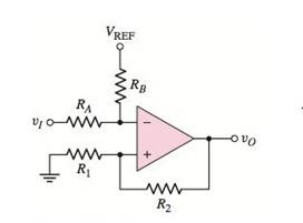
Consider the Schmitt trigger in Figure P15.46. Assume the saturated outputvoltages are
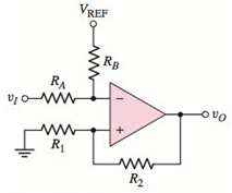
Figure P15.46
(a)
To derive: The expression for the crossover voltage
Answer to Problem 15.46P
The expression for the crossover voltage
Explanation of Solution
Given:
The upper saturated output voltage,
The lowest saturated output voltage,
Calculation:
In an ideal op-amp, the inverting and non-inverting terminal currents are zero. Due to the virtual ground concept, the inverting and non-inverting node voltages are equal.
Given circuit can be represented as
Apply Kirchhoff’s current law at inverting node.
Hence, we get
Apply Kirchhoff’s current law at non-inverting node.
Substitute
When
The upper crossover voltage of Schmitt trigger
Similarly, when
The lower crossover voltage of Schmitt trigger
Conclusion:
Therefore, the expression for the crossover voltage
(b)
To find: the values of
To sketch: The voltage transfer characteristics.
Answer to Problem 15.46P
The required values are
The voltage transfer characteristics are shown in Figure 1
Explanation of Solution
Given:
The circuit voltages are:
Calculation:
The upper crossover voltage is
Therefore, the upper crossover voltage is
The lower crossover voltage is given by,
Therefore, the lower crossover voltage is
The given Schmitt trigger is positive feedback comparator.
Here, the transfer characteristic is a rectangle. Hence, it is called hysteresis which is a dead band. It is so called as the output is not changing
The output remains in the state indefinitely until input voltage crosses the any of the threshold levels.
The voltage transfer characteristics of the given Schmitt trigger is,
Figure 1
Conclusion:
Therefore, the required values are
Therefore, the voltage transfer characteristics are shown in Figure 1.
Want to see more full solutions like this?
Chapter 15 Solutions
Microelectronics: Circuit Analysis and Design


- Q: Explain in details with all figures and equations the modulation index of Amplitude Modulation (AM) and then show the AM wave when the modulation index > 1 , modulation index < 1 and modulation index =1.choose the best case and why.1-draw the three cases.2-write an example.arrow_forwardQ) What is the need of amplitude modulation?arrow_forwardAn analog signal is to be coded by an ADC. The signal contains significant frequencies up to 6MHz. The quantization error in any one sample value must be within ± 0.5% of the peak-to-peak amplitude range of the ADC. How many binary digits must each sample contain? Apply (or equate) the formulas:Δ = Xmax - Xmin / L - 1where Xmax - Xmin = peak-to-peak amplitude range (XRange)eq[n] = Δ/2 (maximum quantization noise)eq[n] = 0.005 XRangearrow_forward
- what is the magnitude gain of Low pass butterworth filter., 6th order.arrow_forwardWhat are the circumstances in which a Kalman filter should be employed?arrow_forwardWe use the DFT to compute the amplitude spectrum of a sampled data sequence with a sampling rate fs =5,000Hz. It requires the frequency resolution to be less than 0.5 Hz. determine the number of data points used by the FFT algorithm and actual frequency resolution in Hz, assuming that the data samples are available for selecting the number of data pointsarrow_forward
- A Delta modulator is used to encode a speech signal x(t) = b sin Wmt band-limited to fm = 10KHz with sampling frequency, fs-100 KHz. For b = +4-volt peak signal voltage, 1) Find the minimum step size to avoid slope overloading. 2) Calculate Signal to quantization noise ratio.arrow_forwardModulation and DemodulationHi! Please answer this thanks!1. Define AM and draw its spectrum?2. Give the significance of modulation index?3. What is the different degree of modulation?4. What are the limitations of square law modulator?arrow_forwardDefine modulation index. Why is it kept low? What is the role of a bandpass filter?arrow_forward
- Draw a block diagram of a simple amplitude modulation. Explain briefly how amplitude modulation is achieved.arrow_forwardNUMERICAL DATA COMMUNICATION An analog signal in sine form is intended to be transmitted to the receiver by pulse code modulation.Given below Define the parameters and answer the questions asked from you. *Peak to peak amplitude = xxx volts *Signal frequency = xxx Hz *Medium height form factor: xxx level 1-)What should be the theoretical minimum sampling frequency for the signal to be reconstructed in the receiver without distortion? 2-) What should be the practical minimum sampling frequency for the signal to be recreated in the receiver without distortion?arrow_forwardHow to calculate the efficiency in frequency modulation and what is the highest value for efficiency in frequency modulationarrow_forward
 Introductory Circuit Analysis (13th Edition)Electrical EngineeringISBN:9780133923605Author:Robert L. BoylestadPublisher:PEARSON
 Delmar's Standard Textbook Of ElectricityElectrical EngineeringISBN:9781337900348Author:Stephen L. HermanPublisher:Cengage Learning
 Programmable Logic ControllersElectrical EngineeringISBN:9780073373843Author:Frank D. PetruzellaPublisher:McGraw-Hill Education
 Fundamentals of Electric CircuitsElectrical EngineeringISBN:9780078028229Author:Charles K Alexander, Matthew SadikuPublisher:McGraw-Hill Education
 Electric Circuits. (11th Edition)Electrical EngineeringISBN:9780134746968Author:James W. Nilsson, Susan RiedelPublisher:PEARSON
 Engineering ElectromagneticsElectrical EngineeringISBN:9780078028151Author:Hayt, William H. (william Hart), Jr, BUCK, John A.Publisher:Mcgraw-hill Education,