
Concept explainers
Videos
The saturated output voltages are
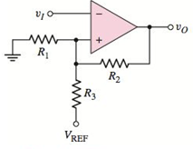
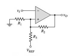
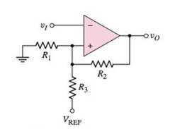
Figure P15.47
(a)
To find: The expression for given crossover voltages.
Answer to Problem 15.47P
The upper crossover voltage of Schmitt trigger is
The lower crossover voltage of Schmitt trigger is
Explanation of Solution
Given:
The given circuit is shown below.
Calculation:
From the above circuit
The inverting node is,
Applying Kirchhoff's current law at non-inverting node:
Substitute
When
The upper crossover voltage of Schmitt trigger is
When
The lower crossover voltage of Schmitt trigger is
Conclusion:
The upper crossover voltage of Schmitt trigger is
The lower crossover voltage of Schmitt trigger is
(b)
To find: The values of
Answer to Problem 15.47P
The required values are
Explanation of Solution
Given:
Saturated output voltage is,
Reference voltage is,
One resistor value is,
Switching point is,
Hysteresis width is
Calculation:
Substitute
Hence,
Substitute
Substitute
Assuming
Hence, we get
Substitute
Therefore, value of
Substitute
Therefore, the value of
Conclusion:
Therefore, the required values are
(c)
To sketch: The voltage transfer characteristics.
Answer to Problem 15.47P
The voltage transfer characteristics are shown in Figure 1.
Explanation of Solution
Given:
Calculation:
The upper crossover voltage of Schmitt trigger is
Therefore, the upper crossover voltage of Schmitt trigger is
The lower crossover voltage of Schmitt trigger is
Therefore, the lower crossover voltage of Schmitt trigger is
Figure 1
Conclusion:
Therefore, the voltage transfer characteristics are shown in Figure 1.
Want to see more full solutions like this?
Chapter 15 Solutions
Microelectronics: Circuit Analysis and Design


- Discuss the ff. topics in outline form 1.Methods of generating SSB (include the block diagram) Filter method Phase shift method Weaver method 2. Block diagram and difference of Low level modulation and high level modulation 3. Low level modulator: circuit diagram and operation Diode modulator Transistor modulator 4. High level modulator: circuit diagram and operation Collector modulatorarrow_forwardWhat are the circumstances in which a Kalman filter should be employed?arrow_forwardFind the output waveform for the multiplexer attached below.arrow_forward
- Explain the concept of PWM (Pulse Width Modulation) and its applications in controlling the intensity of electronic devices in microcontroller-based systems.arrow_forwardWhat do you mean by fractional sampling rate conversion? Explain with an example of converting 48 kHz signal to 44.1 kHz signal using multi-stage fractional sampling rate converterarrow_forwardFIR and IIR filters: merits and disadvantages in digital signal processing?arrow_forward
- A modem (modulator-demodulator) converts digital data to analog signal. There are 3 ways to modulate a digital signal on an analog carrier signal. How that ways will work when amplitude frequency carries 0 and 1. Describe all possible ways.arrow_forwardQ) What is the need of amplitude modulation?arrow_forwardC ompare the amplitude modullation and frequency modulations. What arethe advantages and disadvantages of both systems? (Please original answer not copy from internet)arrow_forward
- For Amplitude shift keying modulation with a carrier frequency of 80MHz and an input bit rate of 10Mbps, determine (a) the minimum nyquist bandwidth and (b) the baud. Answer: a. 10MHz b. 10 baudarrow_forwarddesign a butterworth 1st order low pass filter . explain and calculate its Voarrow_forwardPlease provide at least three different methods for converting analog to digital. What factors led to this shift?arrow_forward
 Introductory Circuit Analysis (13th Edition)Electrical EngineeringISBN:9780133923605Author:Robert L. BoylestadPublisher:PEARSON
 Delmar's Standard Textbook Of ElectricityElectrical EngineeringISBN:9781337900348Author:Stephen L. HermanPublisher:Cengage Learning
 Programmable Logic ControllersElectrical EngineeringISBN:9780073373843Author:Frank D. PetruzellaPublisher:McGraw-Hill Education
 Fundamentals of Electric CircuitsElectrical EngineeringISBN:9780078028229Author:Charles K Alexander, Matthew SadikuPublisher:McGraw-Hill Education
 Electric Circuits. (11th Edition)Electrical EngineeringISBN:9780134746968Author:James W. Nilsson, Susan RiedelPublisher:PEARSON
 Engineering ElectromagneticsElectrical EngineeringISBN:9780078028151Author:Hayt, William H. (william Hart), Jr, BUCK, John A.Publisher:Mcgraw-hill Education,