
(a)
Find the value of
(a)
Answer to Problem 16E
The value of
Explanation of Solution
Given data:
Refer to Figure 15.53 in the textbook.
Formula used:
Write the expression to calculate the impedance of the passive elements resistor, inductor and capacitor in s-domain.
Here,
Calculation:
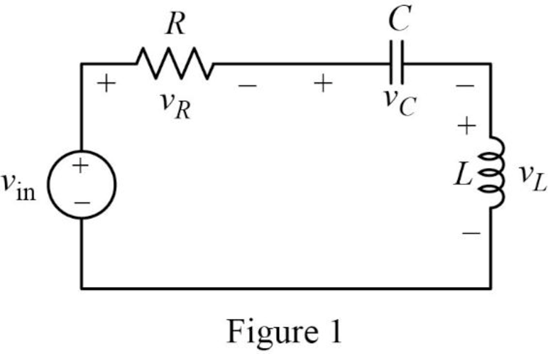
Given that the output voltage should be taken across the inductor in series RLC circuit.
Generally, the transfer function of the series RLC circuit for which the output is taken across the inductor is,
The modified circuit of given circuit is drawn as Figure 1.
The Figure 1 is redrawn as impedance circuit in s-domain in Figure 2 using the equations (1), (2) and (3).
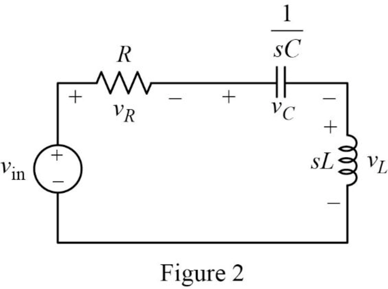
Write the general expression to calculate the transfer function of the circuit in Figure 2.
Here,
Apply Kirchhoff’s voltage law on Figure 2 to find
Rearrange the above equation to find
Substitute
Compare the above equation with the equation (4) to obtain the following values.
Rearrange the equation (6).
Rearrange the above equation to find
Rearrange the equation (7) to find
Substitute
Conclusion:
Thus, the value of
(b)
Find the values of inductor
(b)
Answer to Problem 16E
The value of inductor
Explanation of Solution
Given data:
The value of the resistor
The value of the resonant frequency
Calculation:
Case (i):
From part (a),
Substitute
Rearrange the above equation to find
Rearrange the above equation to find
Rearrange the equation (9).
Rearrange the above equation to find
Substitute
Rearrange the above equation to find
Take square root on both sides of the above equation to find
Substitute
Case (ii):
Substitute
Rearrange the above equation to find
Rearrange the above equation to find
Substitute
Rearrange the above equation to find
Take square root on both sides of the above equation to find
Substitute
Case (iii):
Substitute
Rearrange the above equation to find
Rearrange the above equation to find
Substitute
Rearrange the above equation to find
Take square root on both sides of the above equation to find
Substitute
Conclusion:
Thus, the value of inductor
(c)
Construct the magnitude Bode plots for the three cases
(c)
Explanation of Solution
Calculation:
Simplify the equation (4) to find
Case (i):
Substitute
Case (ii):
Substitute
Case (iii):
Substitute
The equations (15), (16) and (17) are the transfer function of the given series RLC circuit at three different cases
The MATLAB code is given below to sketch the magnitude Bode plots for the three cases using the equations (15), (16) and (17).
MATLAB Code:
clc;
clear all;
close all;
sys1=tf([1 0 0],[1 1000 (25*10^6)]);
sys2=tf([1 0 0],[1 5000 (25*10^6)]);
sys3=tf([1 0 0],[1 10000 (25*10^6)]);
bode(sys1,sys2,sys3)
legend({'sys1','sys2','sys3'},'Location','best')
Output:
The MATLAB output is shown in Figure 3.
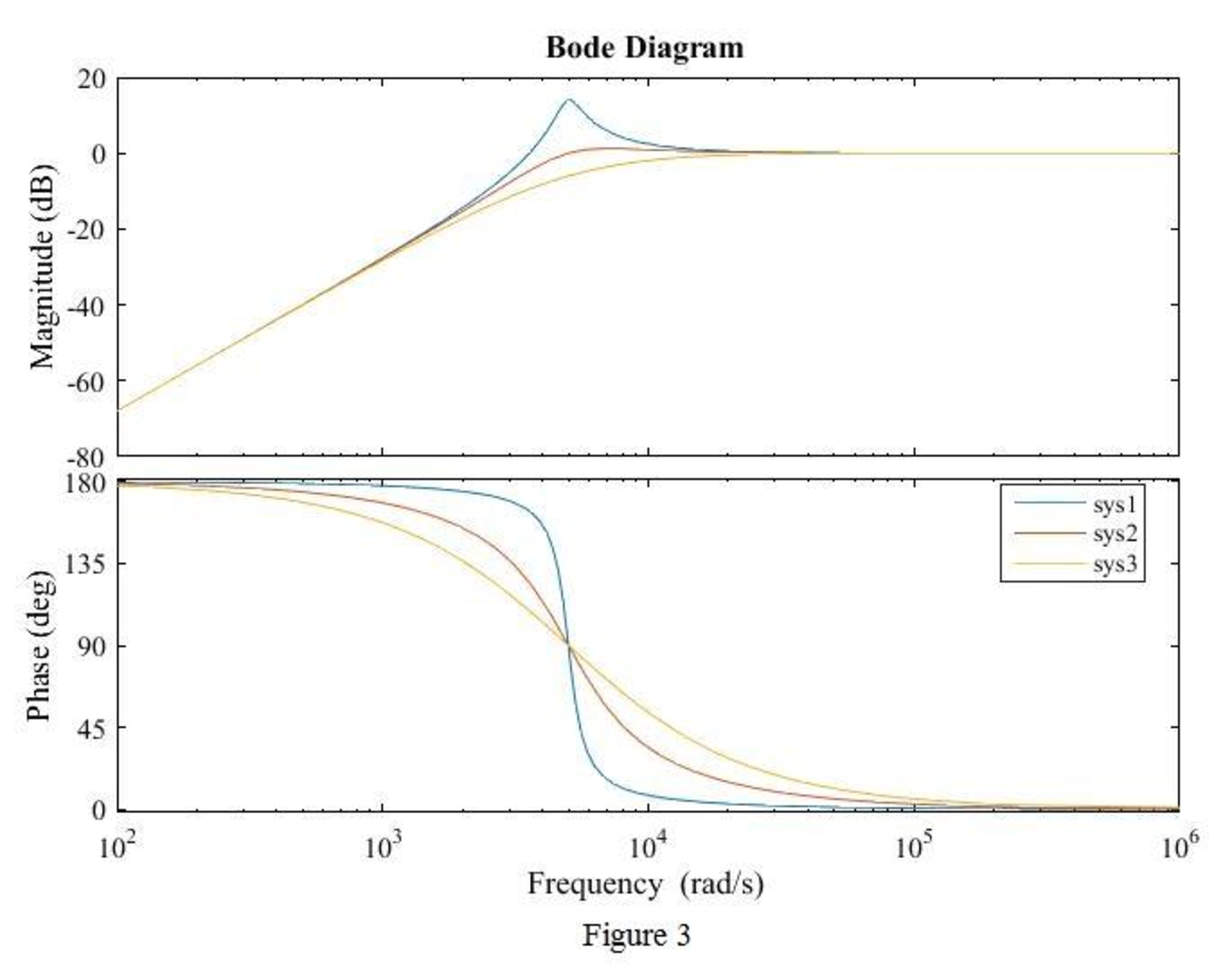
Conclusion:
Thus, the magnitude Bode plot for the three cases
Want to see more full solutions like this?
Chapter 15 Solutions
Loose Leaf for Engineering Circuit Analysis Format: Loose-leaf

- 1. The resistance and inductance of the circuit are 100Ω and 20mH, respectively.1. Find the value of C that makes the voltage response criticallydamped.2. If C is adjusted to give a neper frequency of 5krad/s, find the valueof C and the roots of the characteristic equation.3. If C is adjusted to give a resonant frequency of 20krad/s, find thevalue of C and the roots of the characteristic equation.arrow_forwardFind the gain of the following circuit and the lower and upper cutoff frequencies. (RS = 1 kΩ, R1 = 40 kΩ, R2 = 10kΩ, RC = 15 kΩ, RE = 25 kΩ, RL = 2.2 kΩ, CS = 10 µF, CC = 1 µF, CE = 20 µF, Cbe = 20 pF, Cbc = 30 pF, Vcc = 25 VVT = 26mV, β = 100, ro = infinityarrow_forwardA series RLC circuit is formed using component values R=100 and L=1.5 mH, together with a source that provides a sinusoidal voltage Vs (t). If the quality factor in resonance condition is Q0 = 7, determine: a) the magnitude of the impedance at 500 Mrad s-1b) the current that circulates if vs (t) = 2,5V cos (425 ×10 6t) Note: Vent (input voltage). Vsal (output voltage)arrow_forward
- Find the gain of the following circuit and the lower and upper cutoff frequencies. (RS = 1 kΩ, R1 = 40 kΩ, R2 = 10kΩ, RC = 45 kΩ, RE = 24 kΩ, RL = 2.2 kΩ, CS = 10 µF, CC = 1 µF, CE = 20 µF, Cbe = 20 pF, Cbc = 16 pF, Vcc = 10VVT = 26mV, β = 100, ro = infinityarrow_forwardy[n]+1.2y[n-1]+0.2y[n-2]=x[n]-0.5x[n-1] x[n] is system's input, y[n] is system's output. a) Find the transfer function of the system, H(z). Show the region of convergence by drawing the zero-pole diagram. b) Draw the block diagram representation of the system. c) Find h[n], which is the impulse response of the system. d) Is the frequency response H(e^jw) defined for this system? H(e^jw) if defined?arrow_forwardFigure illustrates the asymptotic Bode plot for a bio-potential amplifier. a. Find the transfer function of the system and express it in the standard form.b. Determine the differential equation that relates the output to the input.c. Find frequency response function of the system.d. Find the output v0(t) of the system if the input is vi(t) = 1 + 0.01cos(0.1t) + 0.001cos(10t) + 0.1cos(1000t)arrow_forward
- Examine the closed loop stability of a system whose open-loop transfer function is given by.G(s) H(s) =1+4s/s^2(1+s )(1+2s) use nyquist plotarrow_forwardMeasurements conducted on a servomechanism show the system response to be: C (t) = 0.3 e 60t + 1.5 e 10t, when subjected to a unit step input. [1].Obtain the expression for the closed-loop transfer function. [2].Determine the undamped natural frequency and damping ratio of the system.arrow_forward4. If R=4 Ω, L=0.2 H and C=80 F are connected in series in the following figure, then Find out (i) ?0, (ii) Q and bandwidth β , (iii) ?1 and ?2, and (iv) amplitude of current at ?0, ?1 and ?2.arrow_forward
- The transfer function of the system whose blog diagram is given below (H (S) = Y (S) / R (S)) remove.arrow_forwardWhen the Nyquist diagram of the given system is drawn, which is the frequency value at which the graph cuts the virtual axis? A 0 rad/sec B 2 rad/sec C 1.732 rad/sec D -2 rad/sec E 1.41 rad/secarrow_forwardall in parallel, a resister 4ohm, inductor 40mH and a capacitor 30nF, (1) derive the impedance and admittance functions in terms of frequency. (2) Calculate the numerical values of the resonant frequency, the dynamic impredance and bandwidtharrow_forward
 Introductory Circuit Analysis (13th Edition)Electrical EngineeringISBN:9780133923605Author:Robert L. BoylestadPublisher:PEARSON
 Delmar's Standard Textbook Of ElectricityElectrical EngineeringISBN:9781337900348Author:Stephen L. HermanPublisher:Cengage Learning
 Programmable Logic ControllersElectrical EngineeringISBN:9780073373843Author:Frank D. PetruzellaPublisher:McGraw-Hill Education
 Fundamentals of Electric CircuitsElectrical EngineeringISBN:9780078028229Author:Charles K Alexander, Matthew SadikuPublisher:McGraw-Hill Education
 Electric Circuits. (11th Edition)Electrical EngineeringISBN:9780134746968Author:James W. Nilsson, Susan RiedelPublisher:PEARSON
 Engineering ElectromagneticsElectrical EngineeringISBN:9780078028151Author:Hayt, William H. (william Hart), Jr, BUCK, John A.Publisher:Mcgraw-hill Education,