
Concept explainers
Videos
For the resistive element in Fig. 15.81:
- Write the current in phasor form.
- Calculate the voltage across the resistor in phasor form.
- Sketch the phasor diagram of the voltage and current.
- Write the voltage in the sinusoidal format.
- Sketch the waveform of the voltage and current.

Fig. 15.81
(a)
The Current in phasor form.
Answer to Problem 1P
The current in phasor form is
Explanation of Solution
Given:
The sinusoidal expression of current is
The resistor value is
Concept Used:
In resistive element network, the network consists of only resistor element.
Resistor does not have any phase angle. It's purely real.
In this, the network current is in phase with voltage.
Total impedance
Current:
Calculation:
In order to convert to phasor form
Conclusion:
Hence, the current in phasor form is
(b)
Voltage across resistor in phasor form.
Answer to Problem 1P
Voltage across resistor in phasor form is
Explanation of Solution
Given:
The sinusoidal expression of current is
The resistor value is
Concept Used:
In resistive element network, the network consists of only resistor element.
Resistor does not have any phase angle. It's purely real.
In this network current are in phase with voltage.
Total impedance
Current:
Calculation:
We know that voltage across resistor is given by
Conclusion:
Hence, the voltage across resistor in phasor form is
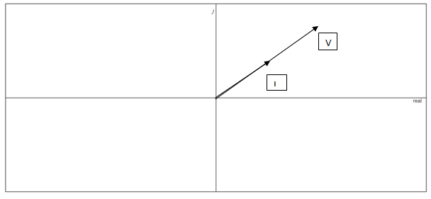
(c)
Phasor diagram of the voltage and current.
Answer to Problem 1P
Phasor diagram of the voltage and current is drawn.
Explanation of Solution
Given:
The sinusoidal expression of current is
The resistor value is
Concept Used:
In resistive element network, the network consists of only resistor element.
Resistor does not have any phase angle. It's purely real.
In this, network current are in phase with voltage.
Total impedance
Current:
Calculation:
Based on the voltage and current value which is already obtained in above part the phasor diagram is drawn. From real axis the angle value is counted.
Conclusion:
Hence, the phasor diagram of the voltage and current is drawn.
(d)
Voltage in the sinusoidal expressions.
Answer to Problem 1P
Voltage in the sinusoidal expressions is
Explanation of Solution
Given:
The sinusoidal expression of current is
The resistor value is
Concept Used:
In resistive element network, the network consists of only resistor element.
Resistor does not have any phase angle. It's purely real.
In this, the network current is in phase with voltage.
Total impedance
Current:
Calculation:
In order to convert to sinusoidal form,
Conclusion:
Hence, voltage in the sinusoidal expressions is
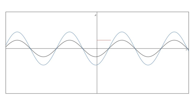
(e)
Waveform of the voltage and current.
Answer to Problem 1P
Waveform of the voltage and current is drawn.
Explanation of Solution
Given:
The sinusoidal expression of current is
The resistor value is
Concept Used:
In resistive element network, the network consists of only resistor element.
Resistor does not have any phase angle. It's purely real.
In this, the network current is in phase with voltage.
Total impedance
Current:
Calculation:
Based on the voltage and current value which is already obtained in the above part, the waveform diagram is drawn. Here, A stands for amplitude.

Conclusion:
Hence, waveform of the voltage and current is drawn.
Want to see more full solutions like this?
Chapter 15 Solutions
Introductory Circuit Analysis (13th Edition)
Additional Engineering Textbook Solutions
ELECTRICITY FOR TRADES (LOOSELEAF)
Programmable Logic Controllers
Electronics Fundamentals: Circuits, Devices & Applications
Engineering Electromagnetics
Electric Circuits. (11th Edition)
Principles Of Electric Circuits


- Write a Matlab code to sketch using plot function, y(t)=3 sin(t) for 3 periodsarrow_forwardEvaluate the following: a) 2 / (1+j) ^4 b) j [ (1+j3) / (1-j2) ] ^2arrow_forwardAn AC Voltage Generator provides 100 V at angular frequency of 500 rad/s to a series RLC, R = 3 ohms, C = 50 uF, L = 10 to 80 mH. Peak Voltage across the capacitor should not exceed 1200 V. A. Determine the AC Source, V(t) and I(t). B. Determine the voltage across the Resistor, VR(t). VR(t) is in phase with I(t). C. What is the average voltage across the resistor, VR?arrow_forward
- The voltage v = 119 sin(100t+50°) V is connected acroos a 8-H inductor. Determine the current in polar form. Write the magnitude only in four decimal places.arrow_forwardThe voltage v = 188 sin(100t+50°) V is connected acroos a 261-µF capacitor. Determine the current at t = 0.008 s. Write the magnitude only in four decimal places.arrow_forward3. A transmission line has a capacitance of 0.1 μF per phase. Determine the inductance of Peterson coilto neutralize the effect of capacitance of (i) complete length of the line, (ii) 97% of the line, (iii) 90%length of the line. The supply frequency is 50 Hz. [(i) 33.80H (ii) 34.84H (iii) 37.55H]arrow_forward
- Calculate the value of Z for the given complex number, where Z1= 5arrow_forwardThe total capacitance and inductance are C=2x10^(-6) F and L=3x10^(-6) H. The physical length of the line is 900 m. (up to 4 decimal places) >time delay t_d >velocity factor k >velocity of propagation v_p in m/s using the distributed parameters >velocity of propagation v_p in m/s using the relative dielectric constant.arrow_forwardsolve for the total complex, apparent, average, and reactive powerarrow_forward
 Introductory Circuit Analysis (13th Edition)Electrical EngineeringISBN:9780133923605Author:Robert L. BoylestadPublisher:PEARSON
 Delmar's Standard Textbook Of ElectricityElectrical EngineeringISBN:9781337900348Author:Stephen L. HermanPublisher:Cengage Learning
 Programmable Logic ControllersElectrical EngineeringISBN:9780073373843Author:Frank D. PetruzellaPublisher:McGraw-Hill Education
 Fundamentals of Electric CircuitsElectrical EngineeringISBN:9780078028229Author:Charles K Alexander, Matthew SadikuPublisher:McGraw-Hill Education
 Electric Circuits. (11th Edition)Electrical EngineeringISBN:9780134746968Author:James W. Nilsson, Susan RiedelPublisher:PEARSON
 Engineering ElectromagneticsElectrical EngineeringISBN:9780078028151Author:Hayt, William H. (william Hart), Jr, BUCK, John A.Publisher:Mcgraw-hill Education,