
Automotive Technology
7th Edition
ISBN: 9781337794213
Author: ERJAVEC, Jack.
Publisher: Cengage,
expand_more
expand_more
format_list_bulleted
Concept explainers
Videos
Textbook Question
Chapter 15, Problem 3ASRQ
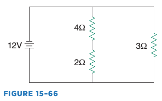
While discussing the circuit shown in Figure 15-66: Technician A says that the total resistance of the circuit is 1 ohm. Technician B says that the current flow through the 6-ohms of resistance is 12 amps. Who is correct?
a. Technician A
b. Technician B
c. Both A and B
d. Neither A nor B
Expert Solution & Answer

Trending nowThis is a popular solution!

Students have asked these similar questions
Show Circuit diagram of the problem and quantity of each part used.
what would be the resistance of a circuit that is open
Need circuit and explain each question...if you do correctly i'll give thumps up
Chapter 15 Solutions
Automotive Technology
Ch. 15 - What is represented by the E, I, and R in the...Ch. 15 - What are the two types of wires and which is the...Ch. 15 - Define voltage drop.Ch. 15 - Define circuit protection.Ch. 15 - Prob. 5SACh. 15 - What is the difference between voltage and...Ch. 15 - What is an SPST switch?Ch. 15 - Solve the parallel circuit for total circuit...Ch. 15 - Prob. 1TFCh. 15 - True or False? An open switch is one that can flow...
Ch. 15 - Which type of resistor is commonly used in...Ch. 15 - Prob. 2MCCh. 15 - Prob. 3MCCh. 15 - Prob. 4MCCh. 15 - Prob. 5MCCh. 15 - Prob. 1ASRQCh. 15 - Prob. 2ASRQCh. 15 - While discussing the circuit shown in Figure...Ch. 15 - While discussing electrical grounds: Technician A...Ch. 15 - Prob. 5ASRQCh. 15 - Prob. 6ASRQCh. 15 - While discussing copper wire: Technician A says...Ch. 15 - While discussing current flow: Technician A says...Ch. 15 - While discussing voltage Technician A says that...Ch. 15 - While discussing the AWG system: Technician A says...
Knowledge Booster


Learn more about
Need a deep-dive on the concept behind this application? Look no further. Learn more about this topic, mechanical-engineering and related others by exploring similar questions and additional content below.Similar questions
- To answer the following questions refer to the circuit shown in Figure 41–10. Assume that the third speed push button is pressed. Explain the sequence of operation for the circuit.arrow_forwardTo answer the following questions refer to the circuit shown in Figure 4110. Assume that the third speed push button is pressed and the motor starts in its first or lowest speed. After a delay of 3 seconds, the motor accelerates to its second speed, but never accelerates to its highest or third speed. Which of the following could cause this problem? a. CR coil is open. b. Coil 2TR is open. c. Coil 1TR is open. d. Coil 1S is open.arrow_forwardTo answer the following questions refer to the circuit shown in Figure 41–14. Assume that contact TS1 closes and the air injection blower motor starts operating, but the high-pressure pump motor does not start. What could cause this problem? Temperature switch TS3 is open. Coil 2M is open. Flow switch FL1 is defective and did not close. Coil TR is open.arrow_forward
- Refer to the circuit shown in Figure 42–17. Assume that the motor is running in the forward direction. When the revers e push button is pressed, the motor continues to run in the forward direction. Which of the following could cause this problem? The normally open side of the reverse push button is not making a complete circuit when pressed. R contactor coil is open. The normally closed side of the reverse push button is not breaking the circuit when the reverse push button is pressed. There is nothing wrong with the circuit. The stop push button must be pressed before the motor will stop running in the forward direction and permit the motor to be reversed.arrow_forwardRefer to the circuit shown in Figure 16-11. Assume that the platform is located on the lower floor. When the UP push button is pressed, the platform rises. When the platform reaches the upper floor, however, the pump does not turn off but continues to run until the overload relay opens the overload contacts. Which of the following could cause this problem? a. The solenoid valve opened when limit switch LS1 opened. b. The UP push button is shorted. c. Limit switch LS1 did not open its contacts. d. Limit switch LS2 contacts did not reclose when the platform began to rise.arrow_forwardRefer to the circuit shown in Figure 16-11. Assume that the platform is located on the bottom floor. When the UP push button is pressed the pump motor does not start. Which of the following could not cause this problem? The contacts of limit switch LS1 are open. The contacts of limit switch LS2 are open. Motor starter coil M is open. The overload contact is open.arrow_forward
- Refer to the circuit shown in Figure 109. In this circuit the jog push button has again been connected incorrectly. The normally closed section of the button has been connected in series with the normally open run push button and the normally open section of the jog button is connecting in parallel with the holding contacts. Explain how this circuit operates.arrow_forwardRefer to the circuit shown in Figure 107. Assume that when the start button is pressed the motor does not start, but when the inch push button is pressed the motor runs at reduced speed. Which of the following could NOT cause this problem? a. The control transformer fuse is blown. b. M starter coil is defective. c. The start push button is defective. d. The stop push button is defective.arrow_forwardRefer to the circuit shown in Figure 15-2. Why is there an overload contact symbol shown in series with the compressor contactor but not the condenser fan contactor or evaporator fan contactor?arrow_forward
- Refer to the circuit shown in Figure 97. Assume that when the forward push button is pressed the motor does not start, but when the reverse push button is pressed the motor will start in the reverse direction. When the stop button is pressed the motor stops running. Which of the following could NOT cause this problem? a. The forward push button is defective. b. The F starter coil is open. c. The overload auxiliary contact is open. d. The normally closed R contact is open.arrow_forwardRefer to the circuit shown in Figure 4221. Assume that the THIRD SPEED push button is pressed. The motor starts in second speed, skipping first speed. After 5 seconds, the motor accelerates to third speed. Which of the following could cause this problem? a. S1 contactor coil is open. b. CR1 contactor coil is open. c. TRl timer coil is open. d. S1 load contacts are shorted.arrow_forwardRefer to the circuit shown in Figure 5-29. Is the thermostat contact normally open, normally closed, normally closed held open, or normally open held closed? Figure 5-29 The contactor contains both load and auxiliary contacts.arrow_forward
arrow_back_ios
SEE MORE QUESTIONS
arrow_forward_ios
Recommended textbooks for you
- Automotive TechnologyMechanical EngineeringISBN:9781337794213Author:ERJAVEC, Jack.Publisher:Cengage,
 Understanding Motor ControlsMechanical EngineeringISBN:9781337798686Author:Stephen L. HermanPublisher:Delmar Cengage Learning
 Refrigeration and Air Conditioning Technology (Mi...Mechanical EngineeringISBN:9781305578296Author:John Tomczyk, Eugene Silberstein, Bill Whitman, Bill JohnsonPublisher:Cengage Learning
Automotive Technology
Mechanical Engineering
ISBN:9781337794213
Author:ERJAVEC, Jack.
Publisher:Cengage,
Understanding Motor Controls
Mechanical Engineering
ISBN:9781337798686
Author:Stephen L. Herman
Publisher:Delmar Cengage Learning
Refrigeration and Air Conditioning Technology (Mi...
Mechanical Engineering
ISBN:9781305578296
Author:John Tomczyk, Eugene Silberstein, Bill Whitman, Bill Johnson
Publisher:Cengage Learning
Engineering Basics - Statics & Forces in Equilibrium; Author: Solid Solutions - Professional Design Solutions;https://www.youtube.com/watch?v=dQBvQ2hJZFg;License: Standard YouTube License, CC-BY