
Concept explainers
Videos
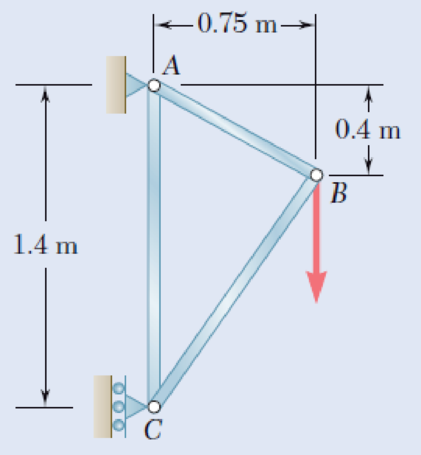
Members AB and BC of the truss shown are made of the same alloy. It is known that a 20-mm-square bar of the same alloy was tested to failure and that an ultimate load of 120 kN was recorded. If a factor of safety of 3.2 is to be achieved for both bars, determine the required cross-sectional area of (a) bar AB, (b) bar AC.
Fig. P1.40 and P1.41
(a)
The required cross sectional area of member AB.
Answer to Problem 40P
The required cross sectional area of AB is
Explanation of Solution
Given information:
The ultimate load
The factor of safety F.S is
The area (a) of square cross section is
Calculation:
Refer to Figure P1.40 in the text book.
Find the length of member
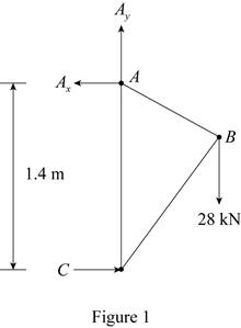
Sketch the free body diagram of truss as shown in Figure 1.
Here,
Refer to Figure 1.
Calculate the horizontal reaction A by using equilibrium Equation as follows:
Calculate the vertical reaction
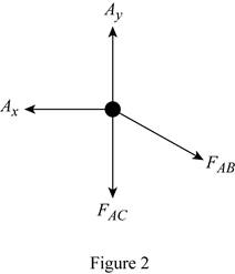
Sketch the free body diagram of joint A as shown in Figure 2.
Refer to Figure P1.40 in the text book.
Refer to Figure 2.
Substitute
Refer to Figure 2.
Substitute
Find the area of test bar (A) using the relation:
Substitute
Find the ultimate load for the material using the formula:
Here,
Substitute
Determine the area of member
Show the expression of factor of safety as follows:
Here,
Modify Equation (5).
Substitute 3.2 for F.S,
Thus, the required cross sectional area of AB is
(b)
The required cross sectional area of AC.
Answer to Problem 40P
The required cross sectional area of AC is
Explanation of Solution
Determine the area of member
Show the expression of factor of safety as follows:
Modify Equation (7).
Substitute 3.2 for F.S,
Thus, the required cross sectional area of AC is
Want to see more full solutions like this?
Chapter 1 Solutions
Mechanics of Materials, 7th Edition


- A 1-inch brass round bar is to be used as a support for a frame. Determine the maximum load that the bar can withstand if the ultimate strength of the brass is 345 MPa.arrow_forwardThe load of 2000 lb is to be supported by the two vertical steel wires for which sY = 70 ksi. Originally wire AB is 60 in. long and wire AC is 60.04 in. long. Determine the cross-sectional area of AB if the load is to be shared equally between both wires. Wire AC has a cross-sectional area of 0.02 in2. Est = 29.0(103) ksi.arrow_forwardTHe bracket shown is made of cold drawn steel with Sy=400MPa and Su=480 MPa, and is fastened to a beam made of the same material by five rivets that are made of a steel with Sy=300 MPa and Sut=365 MPa. The thickness of the bracket and the beam are 12 mm and 16 mm respectively.Diameters of the rivets are 20 mm. What safe load F(steady) can be supported by the riveted joint for a factor of safety of 2. Use distortion energy theory of failure.arrow_forward
- A 2-m length of an aluminum pipe of 240-mm outer diameter and 10-mm wall thickness is used as a short column to carry a 640-kN centric axial load. Knowing that E= 73 GPa and ν=0.33, determine (a) the change in length of the pipe, (b) the change in its outer diam-eter, (c) the change in its wall thicknessarrow_forwardThe length of the 332332 -in.-diameter steel wire CD has been adjusted so that with no load applied, a gap of 116116 in. exists between the end B of the rigid beam ACB and contact point E. Knowing that E = 29 × 106 psi, determine where a 57-lb (w) block should be placed on the beam in order to cause contact between B and E. For contact, x < in.arrow_forwardA 2.75-kN tensile load is applied to a test coupon made from 1.6-mm flat steel plate (E=200 GPa, ν= 0.30). Determine the resulting change (a) in the 50-mm gage length, (b) in the width of portion ABof the test coupon, (c) in the thickness of portion AB, (d)in the cross-sectional area of portion AB.arrow_forward
- determine the diameter of a steel rod that will carry a tensile load of 50000 kg at a stress of 1400 kg per square centimeter.arrow_forwardPLS ANSWER ASAP TY! For the assembly shown, a yoke on a 30 mm diameter rod is attached to a 25 mm thick bracket via 15 mm diameter bolt as shown. The ultimate axial strength in the 30 mm dia. rod is 150 MPa. a)Determine the largest load P (in KN) that can be applied to the rod if a factor of safety of 2.5 with respect to the ultimate axial strength is required. b) What is the tensile axial stress on the rod (in MPa)? c) What is the shear stress on the bolt (in MPa)? d) What is the factor of safety for the 15 mm. dia. bolt with respect to the ultimate shear strength? (in 2 decimal places)arrow_forwardDetermine the thickness of a 130 mm wide uniform plate for safe continuous operation if the plate is to be subjected to a tensile load that has a maximum value of 260 kN and a minimum value of 110 kN. The properties of the plate material are as follows: Endurance limit stress = 235 MPa, and Yield point stress = 310 MPa. The factor of safety based on yield point may be taken as 1.4.arrow_forward
- The five-bolt connection shown must support an applied load of P = 214 kN. If the average shear stress in the bolts must be limited to 249 MPa, determine the minimum bolt diameter that may be used in the connection.arrow_forwardA14-kN tensile load will be applied to a 50-m length of steel wire with E = 200 GPa. Determine the smallest diameter wire that can be used, knowing that the normal stress must not exceed 150 MPa and that the increase in length of the wire must not exceed 25 mm. The smallest diameter that can be used is ___mm?arrow_forwardA 5-kN tensile load will be applied to a 50-m length of steel wire with E = 200 GPa. Determine the smallest diameter wire that can be used, knowing that the normal stress must not exceed 150 MPa and that the increase in length of the wire must not exceed 25 mm.arrow_forward
 Elements Of ElectromagneticsMechanical EngineeringISBN:9780190698614Author:Sadiku, Matthew N. O.Publisher:Oxford University Press
 Mechanics of Materials (10th Edition)Mechanical EngineeringISBN:9780134319650Author:Russell C. HibbelerPublisher:PEARSON
 Thermodynamics: An Engineering ApproachMechanical EngineeringISBN:9781259822674Author:Yunus A. Cengel Dr., Michael A. BolesPublisher:McGraw-Hill Education
 Control Systems EngineeringMechanical EngineeringISBN:9781118170519Author:Norman S. NisePublisher:WILEY
 Mechanics of Materials (MindTap Course List)Mechanical EngineeringISBN:9781337093347Author:Barry J. Goodno, James M. GerePublisher:Cengage Learning
 Engineering Mechanics: StaticsMechanical EngineeringISBN:9781118807330Author:James L. Meriam, L. G. Kraige, J. N. BoltonPublisher:WILEY