
Videos
In an alternative design for the structure of Prob. 1.55, a pin of 10-mm-diameter is to be used at A. Assuming that all other specifications remain unchanged, determine the allowable load P if an overall factor of safety of 3.0 is desired.
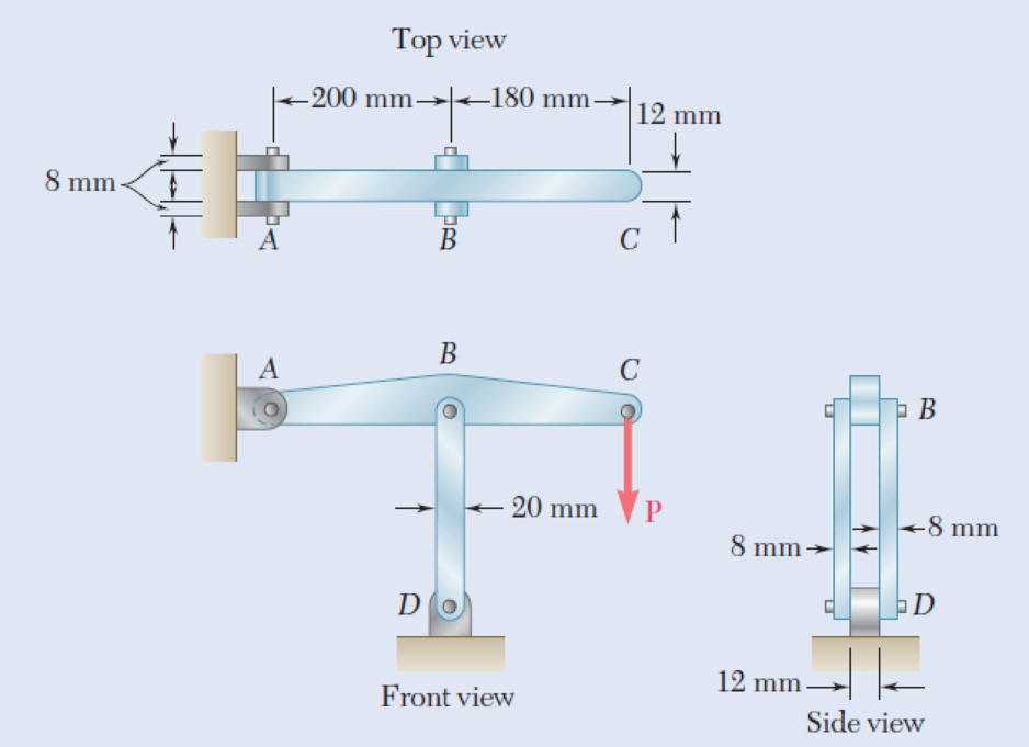
1.55 In the structure shown, an 8-mm-diameter pin is used at A, and 12-mm-diameter pins are used at B and D. Knowing that the ultimate shearing stress is 100 MPa at all connections and that the ultimate normal stress is 250 MPa in each of the two links joining B and D, determine the allowable load P if an overall factor of safety of 3.0 is desired.
Fig. P1.55
The allowable load P when an overall factor of safety of 3.0 is desired.
Answer to Problem 56P
The allowable load P when an overall factor of safety of 3.0 is desired is
Explanation of Solution
Given information:
The diameter (d) of each pin B and D is
The diameter (d) of pin A is
The ultimate shearing stress
The ultimate normal stress
Calculation:
Sketch the free body diagram of ABC as shown in Figure 1.
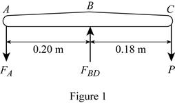
Refer to figure 1.
Take a moment about B.
Take a moment about A.
Find the area of pin at A using the relation:
Substitute
Find the value of
Here, A is the double shear pin A.
Substitute
Find the value of P using the relation:
Substitute
Find the area of double shear pin at B and D using the relation:
Substitute
Find the force in member BD based on double shear in pins at B and D using the relation:
Substitute
Find the value of P using the relation:
Substitute
Find the area based on compression in links BD for one link as follows:
Here, d is the diameter of pin and b is the width of the section.
Substitute
Find the force in member BD of pin at B and D for one link using the relation:
Here, A is the area based on compression in links BD.
Substitute
Find the value of P using the relation:
Substitute
Based on results,
Select the smaller value of P is
Thus, the allowable load P when an overall factor of safety of 3.0 is desired is
Want to see more full solutions like this?
Chapter 1 Solutions
Mechanics of Materials, 7th Edition


- In the structure shown, an 8-mm diameter pin is used at A, and 12-mm diameter pins are used at B and D. Knowing that the ultimate shearing stress is 100 MPa at all connections and that the ultimate normal stress is 250 MPa in each of the two links joining B and D, determine the allowable load P if an overall factor ofsafety of 3.0 is desired.arrow_forwardTwo loads are applied to the bracket BCD as shown. (a) Knowing that the control rod AB is to be made of a steel having an ultimate normal stress of 600 MPa, determine the diameter of the rod for which the factor of safetywith respect to failure will be 3.3. (b) The pin at C is to be made of a steelhaving an ultimate shearing stress of 350 MPa. Determine the diameter ofthe pin C for which the factor of safety with respect to shear will also be 3.3.(c) Determine the required thickness of the bracket supports at C, knowingthat the allowable bearing stress of the steel used is 300 MPa.arrow_forwardIn the structure shown, an 8-mm-diameter pin is used at A and 12 mmdiameter pins are used at B and D. Knowing that the ultimate shearingstress is 100 MPa at all connections and the ultimate normal stress is 250 MPa in each of the two links joining B and D, determine the allowable load P if an overall factor of safety of 3.0 is desired.arrow_forward
- The ABC element is supported by a pin at C and a BD cable. Knowing that the limit load for the BD cable is 150 kN, and the coefficient Safety with respect to cable failure for BD of 3.5 determine the maximum value of the load P that can be supported. Determine the diameter of pin C, knowing that it is made of steel with an admissible stress of σadm = 270 Mpa, and that it is subjected to shear double.arrow_forwardDetermine the largest axial load P that can be safely supported by a flat steel bar consisting of two portions, both 10 mm thick and, respectively, 40 and 60 mm wide, connected by fillets of radius r=8 mm. Assume an allowable normal stress of 165 MPa.arrow_forwardIn the structure shown, an 8 mm diameter pin is used at A, and 12 mm diameter pins are used at B and D. Knowing that the allowable shearing stress is 120 MPa at all connections and that the allowable normal stress and bearing stress is 240 MPa in each of the two links joining B and D, determine the allowable load Parrow_forward
- A load P is supported as shown by a steel pin that has been inserted in a short wooden member hanging from the ceiling. The ultimate strength of the wood used is 60 MPa in tension and 7.5 MPa in shear,while the ultimate strength of the steel is 145 MPa in shear. Knowing that b = 40 mm, c = 55 mm, and d = 12 mm, determine the load P if an overall factor of safety of 3.2 is desired.arrow_forwardTwo links BF are made of steel with a 450-MPa ultimate normal stress and has a 6x12–mm uniform rectangular cross section. Links BF are connected to members ABD and CDEF by 8-mm diameter pins; ABD and CDEF are connected together by a 10-mm diameter pin; CDEF is connected to the support by a 10-mm diameter pin; all of the pins are made of steel with a 170 MPa ultimate shearing stress. Knowing that a factor of safety of 3 is desired, determine the largest load P that may be appliedarrow_forwardA glue-laminated column of 3-m effective length is to be made from boards of 24 x 100-mm cross section. Knowing that for the grade of wood used, E= 11 GPa and the adjusted allowable stress for com-pression parallel to the grain is σC= 9 MPa, determine the number of boards that must be used to support the centric load shown when (a) P= 34 kN, (b) P= 17 kNarrow_forward
- In the truss shown, members AC and AD consist of rods made of the same metal alloy. Knowing that AC is of 1-in. diameter and that the ultimate load for that rod is 75 kips, determine (a) the factor of safety for AC, (b) the required diameter of AD if it is desired that both rods have the same factor of safety.arrow_forwardA steel loop ABCD of length 5 ft and of 3838 -in. diameter is placed as shown around a 1-in.-diameter aluminum rod AC. Cables BE and DF, each of 1212 -in. diameter, are used to apply the load Q. Knowing that the ultimate strength of the steel used for the loop and the cables is 75 ksi, and that the ultimate strength of the aluminum used for the rod is 45 ksi, determine the largest load Q that can be applied if an overall factor of safety of 3 is desired. The largest load Q that can be applied is kips.arrow_forwardA load P is applied to a steel rod supported as shown by an aluminum plate into which a 0.6-in.-diameter hole has been drilled. Knowing that the shearing stress must not exceed 18 ksi in the steel rod and10 ksi in the aluminum plate, determine the largest load P that may be applied to the rod.arrow_forward
 Elements Of ElectromagneticsMechanical EngineeringISBN:9780190698614Author:Sadiku, Matthew N. O.Publisher:Oxford University Press
 Mechanics of Materials (10th Edition)Mechanical EngineeringISBN:9780134319650Author:Russell C. HibbelerPublisher:PEARSON
 Thermodynamics: An Engineering ApproachMechanical EngineeringISBN:9781259822674Author:Yunus A. Cengel Dr., Michael A. BolesPublisher:McGraw-Hill Education
 Control Systems EngineeringMechanical EngineeringISBN:9781118170519Author:Norman S. NisePublisher:WILEY
 Mechanics of Materials (MindTap Course List)Mechanical EngineeringISBN:9781337093347Author:Barry J. Goodno, James M. GerePublisher:Cengage Learning
 Engineering Mechanics: StaticsMechanical EngineeringISBN:9781118807330Author:James L. Meriam, L. G. Kraige, J. N. BoltonPublisher:WILEY