
Videos
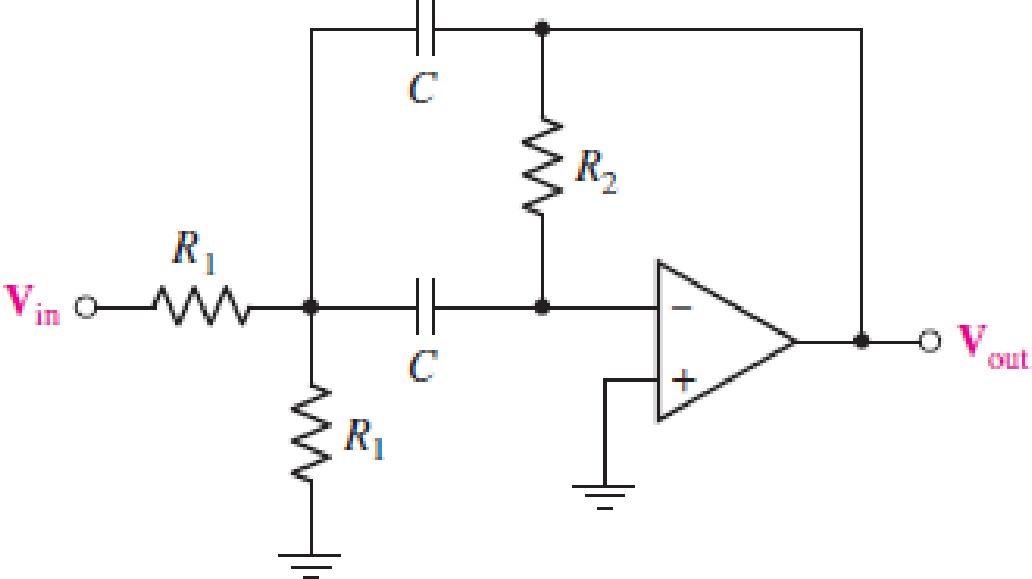
For the circuit in Fig. 15.56, (a) determine the transfer function H(jω) = Vout/Vin in terms of circuit parameters R1, R2, and C; (b) determine the magnitude and phase of the transfer function at ω = 0, 3 × 10⁴ rad/s, and as ω → ∞ for the case where circuit values are R1 = 500 Ω, R2 = 40 kΩ, and C = 10 nF.
FIGURE 15.56
(a)
The transfer function
Answer to Problem 6E
The transfer function
Explanation of Solution
Given data:
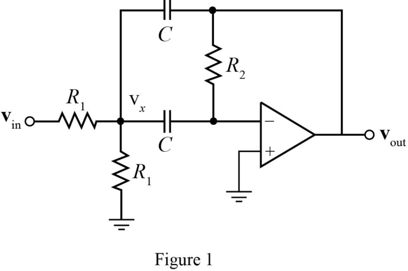
The required diagram is shown in Figure 1.
Calculation:
The equivalent impedance of the capacitor is given as,
The Kirchhoff’s current law equation at node
Here,
The Kirchhoff’s current law equation at
The transfer function
Substitute
Substitute
Conclusion:
Therefore, the transfer function
(b)
The magnitude of transfer function
Answer to Problem 6E
The magnitude of transfer function
Explanation of Solution
Given data:
The resistance
The resistance
The capacitor
The angular frequency
The angular frequency
The angular frequency
Calculation:
The conversion of
The conversion of
The conversion of
The conversion of
The magnitude of transfer function
The phase of transfer function
Substitute
Substitute
The magnitude of transfer function
The magnitude of transfer function
Substitute
Substitute
The magnitude of transfer function
The magnitude of transfer function
Substitute
Substitute
Conclusion:
Therefore, the magnitude of transfer function
Want to see more full solutions like this?
Chapter 15 Solutions
Loose Leaf for Engineering Circuit Analysis Format: Loose-leaf
Additional Engineering Textbook Solutions
Engineering Electromagnetics
ANALYSIS+DESIGN OF LINEAR CIRCUITS(LL)
Basic Engineering Circuit Analysis
Fundamentals of Electric Circuits
Principles and Applications of Electrical Engineering
ELECTRICITY FOR TRADES (LOOSELEAF)


- Find the gain of the following circuit and the lower and upper cutoff frequencies. (RS = 1 kΩ, R1 = 40 kΩ, R2 = 10kΩ, RC = 20 kΩ, RE = 30 kΩ, RL = 2.2 kΩ, CS = 10 µF, CC = 1 µF, CE = 20 µF, Cbe = 20 pF, Cbc = 30 pF,VT = 26mV, β = 100, ro = infinityarrow_forwardRC=10 kΩ, RE=5 kΩ, RL=2.2 kΩ, CS=10 µF, CC=1 µF, CE=20 µF, Cbe=20 pF, Cbc=10 pF,VT=26mV, β=100, ro=sonsuz vcc=20 RS=1 kΩ, R1=40 kΩ, R2=10 Find the gain of the circuit below and the lower and upper cutoff frequencies.arrow_forwardThe voltage transfer function of either low-pass prototype filtershown isH(s)=1s+1. Show that if either circuit is scaled in both magnitude and frequency, thescaled transfer function isH′(s)=1(s/kf)+1.arrow_forward
- In the circuit, the input is "is (t)" and the output is "io (t)". Adhering to the topology shown, and since C = 1 μF, design a low-pass filter that has a resonant frequency ω0 = 200 rad s − 1, a unity gain, and a quality factor of 0.707. To do this, obtain the transfer function H (ω) and the values of R and L.Note: The filter gain is | H (ω) |.arrow_forward1. A series RLC circuit has a Q of 75 and a pass band between half-power frequencies of 160 cps. Calculate the frequency of resonance and upper and lower frequencies of the pass band. 2. A 15.9 uF capacitor and a 15.1 mH inductor are connected in parallel. In series with these units are a variable resistor R and an adjustable device X, joined in series. (a) Determine the kind and size of device X (inductance in Henry or capacitance in Farad) when the circuit is connected to a 50 volt 400 cps source and is adjusted to resonance. (b) For the resonant condition, calculate the value of R if the voltage drop across the paralleled units is to be 100 volts. 3. An impedance coil having a resistance of 30 ohms and a 50 cps inductive reactance of 33.3 ohms is connected to a 125 volt 60 cps source. A series circuit consisting of a 20 ohm resistor and a variable capacitor is then connected in parallel with the coil. (a) for what values of capacitance will the circuit be in resonance? (b)…arrow_forward1. An impedance coil takes 144 watts at a lagging power factor of 0.6. What value of capacitanceand resistance should be connected in series with the coil if the power input to the latter is toremain unchanged and the overall power factor is to be unity (in resonance)? The circuit isenergized by a 120 volt, 60 cps source.2. A series RLC circuit has a Q of 75 and a pass band between half-power frequencies of 160 cps.Calculate the frequency of resonance and upper and lower frequencies of the pass band.3. An impedance coil having a resistance of 30 ohms and a 50 cps inductive reactance of 33.3 ohmsis connected to a 125 volt 60 cps source. A series circuit consisting of a 20 ohm resistor and avariable capacitor is then connected in parallel with the coil. (a) for what values of capacitancewill the circuit be in resonance? (b) calculate the two values of line current for the condition ofresonance.4. A parallel-series filter like that of Fig. 13.10b in the scanned copy of the on page 364 is…arrow_forward
- A summary of the results is as follows: Frequency = 1.01 kHz: Input = 1.51 V; Output = 1.44 V Frequency = 10.06 kHz: Input = 1.37 V; Output = 0.62 V Frequency = 102.8 kHz: Input = 1.31 V; Output = 90 mV The resistor was measured to be 331.4 Ω and the capacitor to be 96.3 nF. (1) Calculate values of the transfer function, using the formula above, at the frequencies that were investigated and compare them to the ratios of the measured output and input voltages at each frequency. A summary of the results is as follows: Frequency = 1.01 kHz: Input = 1.50 V; Output = 1.44 V Frequency = 10.06 kHz: Input = 1.20 V; Output = 0.50 V Frequency = 102.8 kHz: Input = 1.13 V; Output = 70 mV The resistor was measured to be 150.1 Ω and the capacitor to be 233.6 nF. (2) Are the ratios of the output voltage to input voltage for this filter similar to the ratios of the first low-pass filter? Does it make sense based on the transfer function how the ratios compare?arrow_forwardOn the circuit below, assume all initial conditions are 0 and that R = 1kΩ, L = 1mH, and C = 1uF. 1. What is the pass band gain?2. Sketch by hand the bode plots of the system. Clearly explain your reasoning.arrow_forwardIn an LR−C network, the capacitance is 10.61 nF, the bandwidth is 500 Hz and the resonant frequency is 150 kHz. Determine for the circuit the Q-factor, the dynamic resistance, and the magnitude of the impedance when the supply frequency is 0.4% greater than the tuned frequency.arrow_forward
- Consider the open loop transfer function of a system to be a constant value, i.e., G(s)H(s)=50. Using Bode Plots, draw its magnitude and phase response separately.arrow_forwardFind the gain of the following circuit and the lower and upper cutoff frequencies. (RS = 1 kΩ, R1 = 40 kΩ, R2 = 10kΩ, RC = 45 kΩ, RE = 24 kΩ, RL = 2.2 kΩ, CS = 10 µF, CC = 1 µF, CE = 20 µF, Cbe = 20 pF, Cbc = 16 pF, Vcc = 10VVT = 26mV, β = 100, ro = infinityarrow_forwardFind the gain of the following circuit and the lower and upper cutoff frequencies. (RS = 1 kΩ, R1 = 40 kΩ, R2 = 10kΩ, RC = 15 kΩ, RE = 25 kΩ, RL = 2.2 kΩ, CS = 10 µF, CC = 1 µF, CE = 20 µF, Cbe = 20 pF, Cbc = 30 pF, Vcc = 25 VVT = 26mV, β = 100, ro = infinityarrow_forward
 Introductory Circuit Analysis (13th Edition)Electrical EngineeringISBN:9780133923605Author:Robert L. BoylestadPublisher:PEARSON
 Delmar's Standard Textbook Of ElectricityElectrical EngineeringISBN:9781337900348Author:Stephen L. HermanPublisher:Cengage Learning
 Programmable Logic ControllersElectrical EngineeringISBN:9780073373843Author:Frank D. PetruzellaPublisher:McGraw-Hill Education
 Fundamentals of Electric CircuitsElectrical EngineeringISBN:9780078028229Author:Charles K Alexander, Matthew SadikuPublisher:McGraw-Hill Education
 Electric Circuits. (11th Edition)Electrical EngineeringISBN:9780134746968Author:James W. Nilsson, Susan RiedelPublisher:PEARSON
 Engineering ElectromagneticsElectrical EngineeringISBN:9780078028151Author:Hayt, William H. (william Hart), Jr, BUCK, John A.Publisher:Mcgraw-hill Education,