
Videos
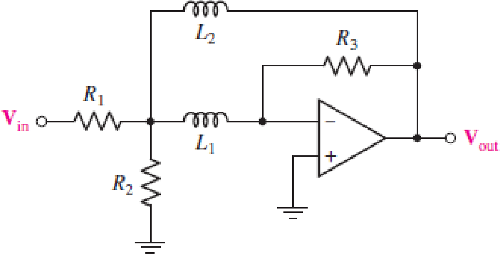
For the circuit in Fig. 15.57, (a) determine the transfer function H(s) = Vout/Vin in terms of circuit parameters R1, R2, R3, L1, and L2; (b) determine the magnitude and phase of the transfer function at ω = 0, 3 × 10³ rad/s, and as ω → ∞ for the case where circuit values are R1 = 2 kΩ, R2 = 2 kΩ, R3 = 20 kΩ, L1 = 2 H, and L2 = 2 H.
FIGURE 15.57
(a)
The transfer function
Answer to Problem 7E
The transfer function
Explanation of Solution
Given data:
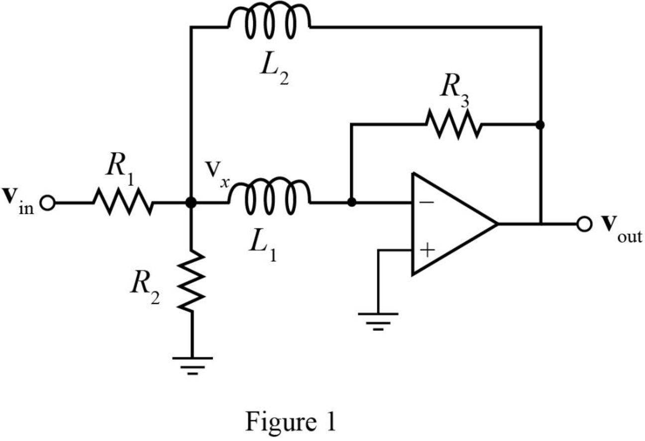
The required diagram is shown in Figure 1.
Calculation:
Assign the node intersecting the two resistors
The KCL equation at node
The KCL equation at node
Here,
Simplifying the equation (2) as,
The transfer function
Substitute
Substitute
Conclusion:
Therefore, the transfer function
(b)
The magnitude of transfer function
Answer to Problem 7E
The magnitude of transfer function
Explanation of Solution
Given data:
The resistance
The resistance
The resistance
The inductance
The inductance
The angular frequency
The angular frequency
The angular frequency
Calculation:
The conversion of
The conversion of
The conversion of
The magnitude of transfer function
The phase of transfer function
Substitute
Substitute
The magnitude of transfer function
The phase of transfer function
Substitute
Substitute
The magnitude of transfer function
The phase of transfer function
Substitute
Substitute
Conclusion:
Therefore, the magnitude of transfer function
Want to see more full solutions like this?
Chapter 15 Solutions
Loose Leaf for Engineering Circuit Analysis Format: Loose-leaf
Additional Engineering Textbook Solutions
Fundamentals of Applied Electromagnetics (7th Edition)
Engineering Electromagnetics
ELECTRICITY FOR TRADES (LOOSELEAF)
Introductory Circuit Analysis (13th Edition)
ANALYSIS+DESIGN OF LINEAR CIRCUITS(LL)
Programmable Logic Controllers


- A series R L C circuit is operating in a resonance mode. The input voltage signal is: u (t ) =150square root of 2 sin (1000 t - 45deg), V . Find the capacitance C, the characteristic impedance ρ, the quality factor Q, the effective (RMS) values of the voltage drops across the passive elements. Given are: R = 10 Ω, L=100 mH. Use the condition for voltage resonance.arrow_forwardIn the circuit, the input is "is (t)" and the output is "io (t)". Adhering to the topology shown, and since C = 1 μF, design a low-pass filter that has a resonant frequency ω0 = 200 rad s − 1, a unity gain, and a quality factor of 0.707. To do this, obtain the transfer function H (ω) and the values of R and L.Note: The filter gain is | H (ω) |.arrow_forwardDraw the circuit diagram of a second-order highpass filter. Given that R=50 Ω, Q s = 0.5, and f 0 =30 MHz, determine the values of L and C.arrow_forward
- y[z]=6cos2(pi×z/4)a.The above equation shows a discrete time signal, y[z] from a device, determine the four point DFT of the sequence.H(ejw) = {1, 0≤|w|≤wC {0, WC |W|< π b.The expression above shows the DTFT of a lowpass filter system. In order to get the impulse response h[n], determine the inverse DTFT of the systemarrow_forward1) from rootlocus fig , Determine damping ratio and ( Wn ) of the closed loop system for K=10.2) Sketch the approximate graph of the Bode magnitude of the transfer function (use K=100). Please answer me part 1,2arrow_forwardA summary of the results is as follows: Frequency = 1.01 kHz: Input = 1.51 V; Output = 1.44 V Frequency = 10.06 kHz: Input = 1.37 V; Output = 0.62 V Frequency = 102.8 kHz: Input = 1.31 V; Output = 90 mV The resistor was measured to be 331.4 Ω and the capacitor to be 96.3 nF. (1) Calculate values of the transfer function, using the formula above, at the frequencies that were investigated and compare them to the ratios of the measured output and input voltages at each frequency. A summary of the results is as follows: Frequency = 1.01 kHz: Input = 1.50 V; Output = 1.44 V Frequency = 10.06 kHz: Input = 1.20 V; Output = 0.50 V Frequency = 102.8 kHz: Input = 1.13 V; Output = 70 mV The resistor was measured to be 150.1 Ω and the capacitor to be 233.6 nF. (2) Are the ratios of the output voltage to input voltage for this filter similar to the ratios of the first low-pass filter? Does it make sense based on the transfer function how the ratios compare?arrow_forward
- 1. A series RLC circuit has a Q of 75 and a pass band between half-power frequencies of 160 cps. Calculate the frequency of resonance and upper and lower frequencies of the pass band. 2. A 15.9 uF capacitor and a 15.1 mH inductor are connected in parallel. In series with these units are a variable resistor R and an adjustable device X, joined in series. (a) Determine the kind and size of device X (inductance in Henry or capacitance in Farad) when the circuit is connected to a 50 volt 400 cps source and is adjusted to resonance. (b) For the resonant condition, calculate the value of R if the voltage drop across the paralleled units is to be 100 volts. 3. An impedance coil having a resistance of 30 ohms and a 50 cps inductive reactance of 33.3 ohms is connected to a 125 volt 60 cps source. A series circuit consisting of a 20 ohm resistor and a variable capacitor is then connected in parallel with the coil. (a) for what values of capacitance will the circuit be in resonance? (b)…arrow_forwardy[n]+1.2y[n-1]+0.2y[n-2]=x[n]-0.5x[n-1] x[n] is system's input, y[n] is system's output. a) Find the transfer function of the system, H(z). Show the region of convergence by drawing the zero-pole diagram. b) Draw the block diagram representation of the system. c) Find h[n], which is the impulse response of the system. d) Is the frequency response H(e^jw) defined for this system? H(e^jw) if defined?arrow_forwardall in parallel, a resister 4ohm, inductor 40mH and a capacitor 30nF, (1) derive the impedance and admittance functions in terms of frequency. (2) Calculate the numerical values of the resonant frequency, the dynamic impredance and bandwidtharrow_forward
- The voltage transfer function of either low-pass prototype filtershown isH(s)=1s+1. Show that if either circuit is scaled in both magnitude and frequency, thescaled transfer function isH′(s)=1(s/kf)+1.arrow_forward21. Plot the magnitude frequency response for the system G(S)=1/(S(1+0.5S)(1+0.1S))). Also determine gain cross over frequency.arrow_forwardConsider the open loop transfer function of a system to be a constant value, i.e., G(s)H(s)=50. Using Bode Plots, draw its magnitude and phase response separately.arrow_forward
 Introductory Circuit Analysis (13th Edition)Electrical EngineeringISBN:9780133923605Author:Robert L. BoylestadPublisher:PEARSON
 Delmar's Standard Textbook Of ElectricityElectrical EngineeringISBN:9781337900348Author:Stephen L. HermanPublisher:Cengage Learning
 Programmable Logic ControllersElectrical EngineeringISBN:9780073373843Author:Frank D. PetruzellaPublisher:McGraw-Hill Education
 Fundamentals of Electric CircuitsElectrical EngineeringISBN:9780078028229Author:Charles K Alexander, Matthew SadikuPublisher:McGraw-Hill Education
 Electric Circuits. (11th Edition)Electrical EngineeringISBN:9780134746968Author:James W. Nilsson, Susan RiedelPublisher:PEARSON
 Engineering ElectromagneticsElectrical EngineeringISBN:9780078028151Author:Hayt, William H. (william Hart), Jr, BUCK, John A.Publisher:Mcgraw-hill Education,