Vector Mechanics for Engineers: Statics and Dynamics
12th Edition
ISBN: 9781259638091
Author: Ferdinand P. Beer, E. Russell Johnston Jr., David Mazurek, Phillip J. Cornwell, Brian Self
Publisher: McGraw-Hill Education
bartleby

Concept explainers

bartleby

Videos

Textbook Question
Book Icon
Chapter 15.1, Problem 15.35P

Two friction disks A and B are brought into contact when the angular velocity of disk A is 240 rpm counterclockwise and disk B is at rest. A period of slipping follows and disk B makes two revolutions before reaching its final angular velocity. Assuming that the angular acceleration of each disk is constant and inversely proportional to the cube of its radius, determine (a) the angular acceleration of each disk, (b) the time during which the disks slip.

Chapter 15.1, Problem 15.35P, Two friction disks A and B are brought into contact when the angular velocity of disk A is 240 rpm

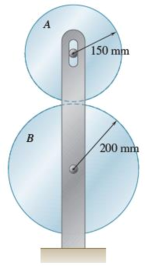
Fig. P15.34 and P15.35

(a)

Expert Solution
Check Mark
To determine

Find the angular acceleration of disk A and B.

Answer to Problem 15.35P

The angular acceleration of disk A and B are 4.34rad/s2(Clockwise)_ and 1.832rad/s2(Clockwise)_.

Explanation of Solution

Given information:

Consider the initial and final angular velocity of disk A are as follows:(ωA)0=240rpm(Counterclockwise) and (ωA)1.

Consider the initial and final angular velocity of disk B are (ωB)0=0rpm and (ωB)1.

Consider the angular acceleration of the disk A and B are denoted by αA and αB.

Consider the angular displacement of the disk B is denoted by θB(Clockwise).

Show the value of the angular displacement θB(Clockwise) as follows:

θB=2rev×(2πradians1rev)=4πradians

The angular acceleration of disk A and B are constant.

The radius of the disk A and B are rA=150mm and rB=200mm.

The angular acceleration of disk A and B are inversely proportional to cube of their radius.

(αBαA)=(rArB)3 (1)

Calculation:

Calculate the final angular velocity of disk A using the relation:

(ωA)1=(ωA)0αAt1

Substitute 240rpm for (ωA)0.

(ωA)1=240rpm×(2πrad/s60rpm)αAt1=8παAt1

Calculate the angular displacement of the disk B using the relation:

θB=(ωB)0t1+12αBt12

Modify above Equation using Equation (1).

θB=(ωB)0t1+12αA(rArB)3t12

Substitute 0 for (ωB)0, 150mm for rA, 200mm for rB, and 4πradians for θB

4π=0+12αA(150200)3t128π=0.421875t12αAt12=8π0.421875αAt12=59.574radians (2)

Calculate the final angular velocity of the disk B using the relation:

(ωB)1=(ωB)0+αBt1

Modify above Equation using Equation (1).

(ωB)1=(ωB)0+αA(rArB)3t1

Substitute 0 for (ωB)0, 150mm for rA, and 200mm for rB.

(ωB)1=0+αA(150200)3t1(ωB)1=0.421875αAt1

Consider the contact point between the disk A and B are denoted by C.

Calculate the velocity at point C using the relation:

vC=rAωA

Substitute 150mm for rA and (8παAt1) for ωA.

vC=150×(8παAt1) (3)

Calculate the velocity at point C using the relation:

vC=rBωB

Substitute 200mm for rB and 0.421875αAt1 for ωB.

vC=200×(0.421875αAt1)=84.375αAt1 (4)

Equate Equation (3) and (4).

150×(8παAt1)=84.375αAt18παAt1=0.5625αAt11.5625αAt1=8παAt1=(8π1.5625)

αAt1=(8π1.5625)αAt1=16.0850rad/s (5)

Divide Equation (1) by (5).

t1=3.7037s (6)

Calculate the angular acceleration of disk A as follows:

Substitute 150mm for rA, 200mm for rB,

αA×(3.7037s)=16.0850rad/sαA=16.0850rad/s3.7037s=4.34rad/s2(Clockwise)

Thus, the angular acceleration of the disk A is 4.34rad/s2(Clockwise)_.

Calculate the angular acceleration of disk B as follows:

Substitute 150mm for rA, 200mm for rB, and 4.34rad/s for αA.

(αB4.34rad/s)=(150200)3αB=4.34(150200)3αB1.832rad/s2

Thus, the angular acceleration of the disk B is 1.832rad/s2(Clockwise)_.

(b)

Expert Solution
Check Mark
To determine

Find the time at which the disk slip.

Answer to Problem 15.35P

The disk slip at time t1=3.70s_.

Explanation of Solution

Given information:

Calculation:

Refer to Part (a).

Refer Equation (6).

The time at which the disk slip is at t1=3.70s.

Thus, the time at which the disk slip is at t1=3.70s_.

Want to see more full solutions like this?

Subscribe now to access step-by-step solutions to millions of textbook problems written by subject matter experts!
Students have asked these similar questions
In order to uncoil electrical wire from a spool fixed to a truck, a worker drives to the left with a speed of vA = 4 m/s. At the same time, a second worker holds the cable as he walks to the right. Knowing that at the instant shown the thickness of wire on the spool is 50 mm and that the 0.6-m-radius spool has an angular velocity of 8 rad/s, determine (a) the instantaneous center of rotation of the spool, (b) the velocity of point D on the spool, (c) the speed of the second worker B.
Knowing that at the instant shown the angular velocity of rod AB is 15 rad/s clockwise, write down the equation of velocity of point B relative to point A. -V_Bi=(-15k)x(-0.2j)   +V_Bj=V_Ai-(15k) x (0.6i+0.25j)   -V_Bi=V_A+(-15k)x(0.2j)   +V_Bj=V_Ai-(omega_BDk) x (-0.6i-0.25j)
Problem 1: In a four bar mechanism, the dimensions of the links are as given below: AB = 50 mm, BC = 66 mm CD = 56 mm and AD = 100 mm At a given instant when |DAB 60o the angular velocity of link AB is 10.5 r/s in CCW direction. Determine, i) Velocity of point C ii) Velocity of point E on link BC when BE = 40 mm iii) The angular velocity of link BC and CD iv) The velocity of an offset point F on link BC, if BF = 45 mm, CF = 30 mm and BCF is read clockwise. v) The velocity of an offset point G on link CD, if CG = 24 mm, DG = 44 mm and DCG is read clockwise. vi) The velocity of rubbing of pins A, B, C and D. The ratio of the pins are 30 mm, 40 mm, 25 mm and 35 mm respectively.

Chapter 15 Solutions

Vector Mechanics for Engineers: Statics and Dynamics

Ch. 15.1 - The angular acceleration of a shaft is defined by...Ch. 15.1 - The assembly shown consists of two rods and a...Ch. 15.1 - In Prob. 15.10, determine the velocity and...Ch. 15.1 - Prob. 15.12PCh. 15.1 - The rectangular block shown rotates about the...Ch. 15.1 - A circular plate of 120-mm radius is supported by...Ch. 15.1 - Prob. 15.15PCh. 15.1 - Prob. 15.16PCh. 15.1 - The earth makes one complete revolution on its...Ch. 15.1 - The sprocket wheel and chain shown are initially...Ch. 15.1 - Prob. 15.19PCh. 15.1 - Prob. 15.20PCh. 15.1 - The rated speed of drum B of the belt sander shown...Ch. 15.1 - The two pulleys shown may be operated with the V...Ch. 15.1 - A cyclist uses a stationary trainer during the...Ch. 15.1 - A gear reduction system consists of three gears A,...Ch. 15.1 - A belt is pulled to the right between cylinders A...Ch. 15.1 - Prob. 15.26PCh. 15.1 - Prob. 15.27PCh. 15.1 - A plastic film moves over two drums. During a 4-s...Ch. 15.1 - Cylinder A is moving downward with a velocity of 3...Ch. 15.1 - The system shown is held at rest by the...Ch. 15.1 - A load is to be raised 20 ft by the hoisting...Ch. 15.1 - A simple friction drive consists of two disks A...Ch. 15.1 - Prob. 15.33PCh. 15.1 - Two friction disks A and B are to be brought into...Ch. 15.1 - Two friction disks A and B are brought into...Ch. 15.1 - Steel tape is being wound onto a spool that...Ch. 15.1 - In a continuous printing process, paper is drawn...Ch. 15.2 - The ball rolls without slipping on the fixed...Ch. 15.2 - Three uniform rodsABC, DCE, and FGHare connected...Ch. 15.2 - Prob. 15.38PCh. 15.2 - An overhead door is guided by wheels at A and B...Ch. 15.2 - A painter is halfway up a 10-m ladder when the...Ch. 15.2 - Rod AB can slide freely along the floor and the...Ch. 15.2 - Rod AB can slide freely along the floor and the...Ch. 15.2 - Rod AB moves over a small wheel at C while end A...Ch. 15.2 - The disk shown moves in the xy plane. Knowing that...Ch. 15.2 - The disk shown moves in the xy plane. Knowing that...Ch. 15.2 - Prob. 15.46PCh. 15.2 - Velocity sensors are placed on a satellite that is...Ch. 15.2 - In the planetary gear system shown, the radius of...Ch. 15.2 - Prob. 15.49PCh. 15.2 - The outer gear C rotates with an angular velocity...Ch. 15.2 - Prob. 15.51PCh. 15.2 - A simplified gear system for a mechanical watch is...Ch. 15.2 - 15.53 and 15.54Arm ACB rotates about point C with...Ch. 15.2 - 15.53 and 15.54Arm ACB rotates about point C with...Ch. 15.2 - Knowing that at the instant shown the angular...Ch. 15.2 - Knowing that at the instant shown the velocity of...Ch. 15.2 - Knowing that the disk has a constant angular...Ch. 15.2 - The disk has a constant angular velocity of 20...Ch. 15.2 - The test rig shown was developed to perform...Ch. 15.2 - Prob. 15.60PCh. 15.2 - In the engine system shown, l = 160 mm and b = 60...Ch. 15.2 - In the engine system shown, l = 160 mm and b = 60...Ch. 15.2 - Knowing that the angular velocity of rod DE is a...Ch. 15.2 - In the position shown, bar AB has an angular...Ch. 15.2 - Prob. 15.65PCh. 15.2 - Prob. 15.66PCh. 15.2 - Prob. 15.67PCh. 15.2 - Prob. 15.68PCh. 15.2 - For the oil pump rig shown, link AB causes the...Ch. 15.2 - Both 6-in.-radius wheels roll without slipping on...Ch. 15.2 - The 80-mm-radius wheel shown rolls to the left...Ch. 15.2 - For the gearing shown, derive an expression for...Ch. 15.3 - The disk rolls without sliding on the fixed...Ch. 15.3 - Prob. 15.6CQCh. 15.3 - A juggling club is thrown vertically into the air....Ch. 15.3 - At the instant shown during deceleration, the...Ch. 15.3 - A helicopter moves horizontally in the x direction...Ch. 15.3 - Prob. 15.76PCh. 15.3 - Prob. 15.77PCh. 15.3 - Prob. 15.78PCh. 15.3 - In order to uncoil electrical wire from a spool...Ch. 15.3 - The arm ABC rotates with an angular velocity of 4...Ch. 15.3 - The double gear rolls on the stationary left rack...Ch. 15.3 - Prob. 15.82PCh. 15.3 - Rod ABD is guided by wheels at A and B that roll...Ch. 15.3 - Knowing that at the instant shown the angular...Ch. 15.3 - Knowing that at the instant shown the velocity of...Ch. 15.3 - A motor at O drives the windshield wiper mechanism...Ch. 15.3 - Prob. 15.88PCh. 15.3 - Small wheels have been attached to the ends of bar...Ch. 15.3 - Prob. 15.90PCh. 15.3 - The disk is released from rest and rolls down the...Ch. 15.3 - Prob. 15.92PCh. 15.3 - Two identical rods ABF and DBE are connected by a...Ch. 15.3 - Arm ABD is connected by pins to a collar at B and...Ch. 15.3 - Two rods ABD and DE are connected to three collars...Ch. 15.3 - Two 500-mm rods are pin-connected at D as shown....Ch. 15.3 - At the instant shown, the velocity of collar A is...Ch. 15.3 - Prob. 15.98PCh. 15.3 - Describe the space centrode and the body centrode...Ch. 15.3 - Describe the space centrode and the body centrode...Ch. 15.3 - Prob. 15.101PCh. 15.3 - Using the method of Sec. 15.3, solve Prob. 15.64....Ch. 15.3 - Using the method of Sec. 15.3, solve Prob. 15.65....Ch. 15.3 - Using the method of Sec. 15.3, solve Prob. 15.38....Ch. 15.4 - A rear-wheel-drive car starts from rest and...Ch. 15.4 - Fig. P15.105 and P15.106 15.105A 5-m steel beam is...Ch. 15.4 - For a 5-m steel beam AE, the acceleration of point...Ch. 15.4 - A 900-mm rod rests on a horizontal table. A force...Ch. 15.4 - In Prob. 15.107, determine the point of the rod...Ch. 15.4 - Knowing that point A is moving to the right at a...Ch. 15.4 - Knowing that at the instant shown crank BC has a...Ch. 15.4 - An automobile travels to the left at a constant...Ch. 15.4 - The 18-in.-radius flywheel is rigidly attached to...Ch. 15.4 - 15.113 and 15.114A 3-in.-radius drum is rigidly...Ch. 15.4 - 15.113 and 15.114A 3-in.-radius drum is rigidly...Ch. 15.4 - A heavy crate is being moved a short distance...Ch. 15.4 - Prob. 15.116PCh. 15.4 - The 100-mm-radius drum rolls without slipping on a...Ch. 15.4 - In the planetary gear system shown, the radius of...Ch. 15.4 - The 200-mm-radius disk rolls without sliding on...Ch. 15.4 - Knowing that crank AB rotates about point A with a...Ch. 15.4 - Knowing that crank AB rotates about point A with a...Ch. 15.4 - In the two-cylinder air compressor shown, the...Ch. 15.4 - The right leg of an athlete on a rowing machine...Ch. 15.4 - Arm AB has a constant angular velocity of 16 rad/s...Ch. 15.4 - Arm AB has a constant angular velocity of 16 rad/s...Ch. 15.4 - A straight rack rests on a gear of radius r = 3...Ch. 15.4 - The elliptical exercise machine has fixed axes of...Ch. 15.4 - The elliptical exercise machine has fixed axes of...Ch. 15.4 - Knowing that the angular velocity of rod DE is a...Ch. 15.4 - Knowing that at the instant shown bar DE has an...Ch. 15.4 - 15.131 and 15.132Knowing that at the instant shown...Ch. 15.4 - 15.131 and 15.132Knowing that at the instant shown...Ch. 15.4 - 15.133 and 15.134Knowing that at the instant shown...Ch. 15.4 - 15.133 and 15.134Knowing that at the instant shown...Ch. 15.4 - Prob. 15.135PCh. 15.4 - For the oil pump rig shown, link AB causes the...Ch. 15.4 - Denoting by rA the position vector of a point A of...Ch. 15.4 - Prob. 15.138PCh. 15.4 - Prob. 15.139PCh. 15.4 - Prob. 15.140PCh. 15.4 - Prob. 15.141PCh. 15.4 - Prob. 15.142PCh. 15.4 - Prob. 15.143PCh. 15.4 - Crank AB rotates with a constant clockwise angular...Ch. 15.4 - Crank AB rotates with a constant clockwise angular...Ch. 15.4 - Solve the engine system from Sample Prob. 15.15...Ch. 15.4 - Prob. 15.147PCh. 15.4 - Prob. 15.148PCh. 15.4 - Prob. 15.149PCh. 15.5 - A person walks radially inward on a platform that...Ch. 15.5 - The motion of pin P is guided by slots cut in rods...Ch. 15.5 - The motion of pin P is guided by slots cut in rods...Ch. 15.5 - 15.152 and 15.153Two rotating rods are connected...Ch. 15.5 - 15.152 and 15.153Two rotating rods are connected...Ch. 15.5 - Pin P is attached to the wheel shown and slides in...Ch. 15.5 - Knowing that at the instant shown the angular...Ch. 15.5 - Prob. 15.156PCh. 15.5 - The motion of pin P is guided by slots cut in rods...Ch. 15.5 - Prob. 15.158PCh. 15.5 - Prob. 15.159PCh. 15.5 - Prob. 15.160PCh. 15.5 - Pin P is attached to the collar shown; the motion...Ch. 15.5 - Prob. 15.162PCh. 15.5 - Prob. 15.163PCh. 15.5 - At the instant shown, the length of the boom AB is...Ch. 15.5 - At the instant shown, the length of the boom AB is...Ch. 15.5 - Prob. 15.166PCh. 15.5 - Prob. 15.167PCh. 15.5 - Prob. 15.168PCh. 15.5 - 15.168 and 15.169A chain is looped around two...Ch. 15.5 - Prob. 15.170PCh. 15.5 - Prob. 15.171PCh. 15.5 - The collar P slides outward at a constant relative...Ch. 15.5 - Pin P slides in a circular slot cut in the plate...Ch. 15.5 - Prob. 15.174PCh. 15.5 - Prob. 15.175PCh. 15.5 - Knowing that at the instant shown the rod attached...Ch. 15.5 - Prob. 15.177PCh. 15.5 - In Prob. 15.177, determine the angular velocity...Ch. 15.5 - At the instant shown, bar BC has an angular...Ch. 15.5 - Prob. 15.180PCh. 15.5 - Rod AB passes through a collar that is welded to...Ch. 15.5 - Prob. 15.182PCh. 15.5 - Prob. 15.183PCh. 15.6 - The bowling ball shown rolls without slipping on...Ch. 15.6 - Prob. 15.185PCh. 15.6 - Prob. 15.186PCh. 15.6 - Prob. 15.187PCh. 15.6 - The rotor of an electric motor rotates at the...Ch. 15.6 - Prob. 15.189PCh. 15.6 - Prob. 15.190PCh. 15.6 - In the system shown, disk A is free to rotate...Ch. 15.6 - Prob. 15.192PCh. 15.6 - Prob. 15.193PCh. 15.6 - A radar system is used to track a new experimental...Ch. 15.6 - A 3-in.-radius disk spins at the constant rate 2 =...Ch. 15.6 - Prob. 15.196PCh. 15.6 - The cone shown rolls on the zx plane with its apex...Ch. 15.6 - At the instant shown, the robotic arm ABC is being...Ch. 15.6 - Prob. 15.199PCh. 15.6 - Prob. 15.200PCh. 15.6 - Several rods are brazed together to form the...Ch. 15.6 - In Prob. 15.201, the speed of point B is known to...Ch. 15.6 - Prob. 15.203PCh. 15.6 - Prob. 15.204PCh. 15.6 - Rod BC and BD are each 840 mm long and are...Ch. 15.6 - Rod AB is connected by ball-and-socket joints to...Ch. 15.6 - Prob. 15.207PCh. 15.6 - Prob. 15.208PCh. 15.6 - Prob. 15.209PCh. 15.6 - Prob. 15.210PCh. 15.6 - Prob. 15.211PCh. 15.6 - Prob. 15.212PCh. 15.6 - Prob. 15.213PCh. 15.6 - Prob. 15.214PCh. 15.6 - In Prob. 15.205, determine the acceleration of...Ch. 15.6 - In Prob. 15.206, determine the acceleration of...Ch. 15.6 - In Prob. 15.207, determine the acceleration of...Ch. 15.6 - Prob. 15.218PCh. 15.6 - Prob. 15.219PCh. 15.7 - A flight simulator is used to train pilots on how...Ch. 15.7 - A flight simulator is used to train pilots on how...Ch. 15.7 - Prob. 15.222PCh. 15.7 - Prob. 15.223PCh. 15.7 - Prob. 15.224PCh. 15.7 - The bent rod shown rotates at the constant rate of...Ch. 15.7 - The bent pipe shown rotates at the constant rate 1...Ch. 15.7 - The circular plate shown rotates about its...Ch. 15.7 - Prob. 15.228PCh. 15.7 - Prob. 15.229PCh. 15.7 - Prob. 15.230PCh. 15.7 - Prob. 15.231PCh. 15.7 - Using the method of Sec. 15.7A, solve Prob....Ch. 15.7 - Prob. 15.233PCh. 15.7 - Prob. 15.234PCh. 15.7 - Prob. 15.235PCh. 15.7 - The arm AB of length 16 ft is used to provide an...Ch. 15.7 - The remote manipulator system (RMS) shown is used...Ch. 15.7 - A disk with a radius of 120 mm rotates at the...Ch. 15.7 - Prob. 15.239PCh. 15.7 - Prob. 15.240PCh. 15.7 - Prob. 15.241PCh. 15.7 - The cylinder shown rotates at the constant rate 2...Ch. 15.7 - Prob. 15.243PCh. 15.7 - Prob. 15.244PCh. 15.7 - Prob. 15.245PCh. 15.7 - Prob. 15.246PCh. 15.7 - Prob. 15.247PCh. 15 - A wheel moves in the xy plane in such a way that...Ch. 15 - Two blocks and a pulley are connected by...Ch. 15 - A baseball pitching machine is designed to deliver...Ch. 15 - The flywheel OD on the elliptical machine analyzed...Ch. 15 - The roller at point A on the elliptical machine...Ch. 15 - Knowing that at the instant shown rod AB has zero...Ch. 15 - Rod AB is attached to a collar at A and is fitted...Ch. 15 - Prob. 15.255RPCh. 15 - A disk of 0.15-m radius rotates at the constant...Ch. 15 - Prob. 15.257RPCh. 15 - Prob. 15.258RPCh. 15 - In the position shown, the thin rod moves at a...
Knowledge Booster
Background pattern image
Mechanical Engineering
Learn more about
Need a deep-dive on the concept behind this application? Look no further. Learn more about this topic, mechanical-engineering and related others by exploring similar questions and additional content below.
Similar questions
Recommended textbooks for you
Text book image
Elements Of Electromagnetics
Mechanical Engineering
ISBN:9780190698614
Author:Sadiku, Matthew N. O.
Publisher:Oxford University Press
Text book image
Mechanics of Materials (10th Edition)
Mechanical Engineering
ISBN:9780134319650
Author:Russell C. Hibbeler
Publisher:PEARSON
Text book image
Thermodynamics: An Engineering Approach
Mechanical Engineering
ISBN:9781259822674
Author:Yunus A. Cengel Dr., Michael A. Boles
Publisher:McGraw-Hill Education
Text book image
Control Systems Engineering
Mechanical Engineering
ISBN:9781118170519
Author:Norman S. Nise
Publisher:WILEY
Text book image
Mechanics of Materials (MindTap Course List)
Mechanical Engineering
ISBN:9781337093347
Author:Barry J. Goodno, James M. Gere
Publisher:Cengage Learning
Text book image
Engineering Mechanics: Statics
Mechanical Engineering
ISBN:9781118807330
Author:James L. Meriam, L. G. Kraige, J. N. Bolton
Publisher:WILEY
Dynamics - Lesson 1: Introduction and Constant Acceleration Equations; Author: Jeff Hanson;https://www.youtube.com/watch?v=7aMiZ3b0Ieg;License: Standard YouTube License, CC-BY