
Loose Leaf for Engineering Circuit Analysis Format: Loose-leaf
9th Edition
ISBN: 9781259989452
Author: Hayt
Publisher: Mcgraw Hill Publishers
expand_more
expand_more
format_list_bulleted
Concept explainers
Videos
Textbook Question
Chapter 15.6, Problem 12P
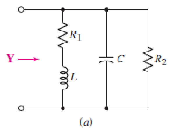
Referring to the circuit of Fig. 15.25a, let R1 = 1 kΩ and C = 2.533 pF. Determine the inductance necessary to select a resonant frequency of 1 MHz. (Hint: Recall that ω = 2π f.)
Expert Solution & Answer
Want to see the full answer?
Check out a sample textbook solution
Students have asked these similar questions
A series R L C circuit is operating in a resonance mode. The input voltage signal is: u (t ) =150square root of 2 sin (1000 t - 45deg), V . Find the capacitance C, the characteristic impedance ρ, the quality factor
Q, the effective (RMS) values of the voltage drops across the passive elements. Given are: R = 10 Ω, L=100 mH. Use the condition for voltage resonance.
An FM signal, eFM = 50 sin [2π(800k)t - 4 sin 2π(5k)t] is produced by a frequency modulator with -500Hz/V frequency deviation constant. Determine (a)Determine the equation of the carrier signal (b) What is the equation of the modulating signal (c) Determine the approximate bandwidth of the FM signal (use Carson’s Approximation)
21. Plot the magnitude frequency response for the system G(S)=1/(S(1+0.5S)(1+0.1S))). Also determine gain cross over frequency.
Chapter 15 Solutions
Loose Leaf for Engineering Circuit Analysis Format: Loose-leaf
Ch. 15.1 - Write an expression for the transfer function of...Ch. 15.2 - Calculate HdB at = 146 rad/s if H(s) equals (a)...Ch. 15.2 - Prob. 3PCh. 15.2 - Draw the Bode phase plot for the transfer function...Ch. 15.2 - Construct a Bode magnitude plot for H(s) equal to...Ch. 15.2 - Draw the Bode phase plot for H(s) equal to (a)...Ch. 15.2 - Prob. 7PCh. 15.3 - A parallel resonant circuit is composed of the...Ch. 15.3 - Prob. 9PCh. 15.4 - A marginally high-Q parallel resonant circuit has...
Ch. 15.5 - A series resonant circuit has a bandwidth of 100...Ch. 15.6 - Referring to the circuit of Fig. 15.25a, let R1 =...Ch. 15.6 - Prob. 13PCh. 15.6 - Prob. 14PCh. 15.6 - The series combination of 10 and 10 nF is in...Ch. 15.7 - A parallel resonant circuit is defined by C = 0.01...Ch. 15.8 - Design a high-pass filter with a cutoff frequency...Ch. 15.8 - Design a bandpass filter with a low-frequency...Ch. 15.8 - Design a low-pass filter circuit with a gain of 30...Ch. 15 - For the RL circuit in Fig. 15.52, (a) determine...Ch. 15 - For the RL circuit in Fig. 15.52, switch the...Ch. 15 - Examine the series RLC circuit in Fig. 15.53, with...Ch. 15 - For the circuit in Fig. 15.54, (a) derive an...Ch. 15 - For the circuit in Fig. 15.55, (a) derive an...Ch. 15 - For the circuit in Fig. 15.56, (a) determine the...Ch. 15 - For the circuit in Fig. 15.57, (a) determine the...Ch. 15 - Sketch the Bode magnitude and phase plots for the...Ch. 15 - Use the Bode approach to sketch the magnitude of...Ch. 15 - If a particular network is described by transfer...Ch. 15 - Use MATLAB to plot the magnitude and phase Bode...Ch. 15 - Determine the Bode magnitude plot for the...Ch. 15 - Determine the Bode magnitude and phase plot for...Ch. 15 - Prob. 15ECh. 15 - Prob. 16ECh. 15 - For the circuit of Fig. 15.56, construct a...Ch. 15 - Construct a magnitude and phase Bode plot for the...Ch. 15 - For the circuit in Fig. 15.54, use LTspice to...Ch. 15 - For the circuit in Fig. 15.55, use LTspice to...Ch. 15 - Prob. 21ECh. 15 - A certain parallel RLC circuit is built using...Ch. 15 - A parallel RLC network is constructed using R = 5...Ch. 15 - Prob. 24ECh. 15 - Delete the 2 resistor in the network of Fig....Ch. 15 - Delete the 1 resistor in the network of Fig....Ch. 15 - Prob. 28ECh. 15 - Prob. 29ECh. 15 - Prob. 30ECh. 15 - A parallel RLC network is constructed with a 200 H...Ch. 15 - Prob. 32ECh. 15 - A parallel RLC circuit is constructed such that it...Ch. 15 - Prob. 34ECh. 15 - Prob. 35ECh. 15 - An RLC circuit is constructed using R = 5 , L = 20...Ch. 15 - Prob. 37ECh. 15 - Prob. 38ECh. 15 - For the network of Fig. 15.25a, R1 = 100 , R2 =...Ch. 15 - Assuming an operating frequency of 200 rad/s, find...Ch. 15 - Prob. 41ECh. 15 - Prob. 42ECh. 15 - For the circuit shown in Fig. 15.64, the voltage...Ch. 15 - Prob. 44ECh. 15 - Prob. 45ECh. 15 - Prob. 46ECh. 15 - The filter shown in Fig. 15.66a has the response...Ch. 15 - Prob. 48ECh. 15 - Examine the filter for the circuit in Fig. 15.68....Ch. 15 - Examine the filter for the circuit in Fig. 15.69....Ch. 15 - (a)Design a high-pass filter with a corner...Ch. 15 - (a) Design a low-pass filter with a break...Ch. 15 - Prob. 53ECh. 15 - Prob. 54ECh. 15 - Design a low-pass filter characterized by a...Ch. 15 - Prob. 56ECh. 15 - The circuit in Fig. 15.70 is known as a notch...Ch. 15 - (a) Design a two-stage op amp filter circuit with...Ch. 15 - Design a circuit which removes the entire audio...Ch. 15 - Prob. 61ECh. 15 - If a high-pass filter is required having gain of 6...Ch. 15 - (a) Design a second-order high-pass Butterworth...Ch. 15 - Design a fourth-order high-pass Butterworth filter...Ch. 15 - (a) Design a Sallen-Key low-pass filter with a...Ch. 15 - (a) Design a Sallen-Key low-pass filter with a...Ch. 15 - A piezoelectric sensor has an equivalent circuit...Ch. 15 - Design a parallel resonant circuit for an AM radio...Ch. 15 - The network of Fig. 15.72 was implemented as a...Ch. 15 - Determine the effect of component tolerance on the...
Additional Engineering Textbook Solutions
Find more solutions based on key concepts
Write the nodal equations for the network of Fig. 8.137 using the general approach. Find the nodal voltages usi...
Introductory Circuit Analysis (13th Edition)
Analog Voltmeter Design Figure P2-98(a) shows a voltmeter circuit consisting of a D'Arsonval meter, two series ...
ANALYSIS+DESIGN OF LINEAR CIRCUITS(LL)
Assume a telephone signal travels through a cable at two-thirds the speed of light. How long does it take the s...
Electric Circuits (10th Edition)
What is the color code for a 365- five-band precision resistor with a tolerance of 5 percent?
ELECTRICITY FOR TRADES (LOOSELEAF)
How many coulombs do 93.8 1016 electrons represent?
Principles Of Electric Circuits
Three point charges of equal magnitude q, that will yield a zero net electric field at the origin.
Engineering Electromagnetics
Knowledge Booster


Learn more about
Need a deep-dive on the concept behind this application? Look no further. Learn more about this topic, electrical-engineering and related others by exploring similar questions and additional content below.Similar questions
- 1. A series RLC circuit has a Q of 75 and a pass band between half-power frequencies of 160 cps. Calculate the frequency of resonance and upper and lower frequencies of the pass band. 2. A 15.9 uF capacitor and a 15.1 mH inductor are connected in parallel. In series with these units are a variable resistor R and an adjustable device X, joined in series. (a) Determine the kind and size of device X (inductance in Henry or capacitance in Farad) when the circuit is connected to a 50 volt 400 cps source and is adjusted to resonance. (b) For the resonant condition, calculate the value of R if the voltage drop across the paralleled units is to be 100 volts. 3. An impedance coil having a resistance of 30 ohms and a 50 cps inductive reactance of 33.3 ohms is connected to a 125 volt 60 cps source. A series circuit consisting of a 20 ohm resistor and a variable capacitor is then connected in parallel with the coil. (a) for what values of capacitance will the circuit be in resonance? (b)…arrow_forward6) An angle-modulated signal has the form s(t) = 100 cos (2π fc t + 3 sin (2πfm t)) Where fc= 5 MHz and fm = 500 Hz. Assuming that it is an FM signal, determine and index of modulation and the bandwidth of the signal.arrow_forwardAssuming that an oscilloscope displays a Vmax of 5.22V and Vmin of 1.33V. Calculate the percentage of modulation. Three (3) AM broadcast stations are spaced at 18 kHz, beginning at 73 kHz. Each station is allowed to transmit modulating up to 6 kHz. Compute for the upper and lower sidebands of each station and plot it in the frequency domain. Given a Vmax of 7.45V and a modulation index of 0.691, calculate for Vmin. A station is given a carrier frequency of 88 kHz. Having a modulating frequency of 12 kHz, compute for the upper and lower sidebands of the station.arrow_forward
- In the circuit given above, the frequency a is 1.7 kHz in the amplitude spectrum drawn when Ri=0. The capacitance of the capacitor for the same circuit is 0.5 microF.What should be the value of the resistor R so that the quality factor remains unchanged at 2.0 when the resistor Ri is 1.9 ohms?arrow_forward3. Given a pass-band amplifier in 66MHz, design a frequency mixer that receives a 199.25 MHz signal and produce a 67.25 MHz signalarrow_forwardAn FM transmitter is determined to have a transmitter sensitivity of 410.348Hz/V. If the modulating signal is designed to be 27.397V, and the modulation index is kept to be at 2.5, solve for the total bandwidth according to carson's rule.arrow_forward
- 2. An FM signal is represented by the equation v(t) = 12 sin (6.28x10⁸ t + 8 sin 1450t). Determine the unmodulated carrier frequency, the modulating frequency and the modulation index. Note: Please write clearlyarrow_forwardA series RLC circuit in which R = 1.00 Ω, L = 1.00 mH, and C = 1.00 nF is connected to an AC source delivering 1.00 V (rms). (a) Make a precise graph of the power delivered to the circuit as a function of the frequency and (b) verify that the full width of the resonance peak at halfmaximum is R/2πL.arrow_forwardThe cascaded RF filters of a TRF receiver have 590µH inductors. The variable capacitors have a capacitance tuning ratio of 6.5. With these filters, the receiver can tune to a minimum of 500kHz.a. determine the maximum capacitance of the variable capacitors b. determine the minimum capacitance of the variable capacitors c. what is the maximum resonant frequency of the RF filters?arrow_forward
- Q3. An AM (DSB) signal is given by x(t) = 20(1 + 0.5 cos(4000nt) + 0.5 cos(6000nt)) cos(20000nt). a) Sketch the frequency spectrum of x.(t). b) Find the average power content of each spectral component. c) Calculate the modulation index. d) Design a demodulator using block diagram and indicate the outputs of each block. e) Propose a method to reduce transmission bandwidth of the system.arrow_forwardA series RLC circuit is formed using component values R=100 and L=1.5 mH, together with a source that provides a sinusoidal voltage Vs (t). If the quality factor in resonance condition is Q0 = 7, determine: a) the magnitude of the impedance at 500 Mrad s-1b) the current that circulates if vs (t) = 2,5V cos (425 ×10 6t) Note: Vent (input voltage). Vsal (output voltage)arrow_forwardthe carrier signal is represented as, x(t) = 2cos(10nt), find 1- Its frequency component. 2- Its frequency spectrum. 3- Draw all input/output signals.arrow_forward
arrow_back_ios
SEE MORE QUESTIONS
arrow_forward_ios
Recommended textbooks for you
 Introductory Circuit Analysis (13th Edition)Electrical EngineeringISBN:9780133923605Author:Robert L. BoylestadPublisher:PEARSON
 Delmar's Standard Textbook Of ElectricityElectrical EngineeringISBN:9781337900348Author:Stephen L. HermanPublisher:Cengage Learning
 Programmable Logic ControllersElectrical EngineeringISBN:9780073373843Author:Frank D. PetruzellaPublisher:McGraw-Hill Education
 Fundamentals of Electric CircuitsElectrical EngineeringISBN:9780078028229Author:Charles K Alexander, Matthew SadikuPublisher:McGraw-Hill Education
 Electric Circuits. (11th Edition)Electrical EngineeringISBN:9780134746968Author:James W. Nilsson, Susan RiedelPublisher:PEARSON
 Engineering ElectromagneticsElectrical EngineeringISBN:9780078028151Author:Hayt, William H. (william Hart), Jr, BUCK, John A.Publisher:Mcgraw-hill Education,
Introductory Circuit Analysis (13th Edition)
Electrical Engineering
ISBN:9780133923605
Author:Robert L. Boylestad
Publisher:PEARSON
Delmar's Standard Textbook Of Electricity
Electrical Engineering
ISBN:9781337900348
Author:Stephen L. Herman
Publisher:Cengage Learning
Programmable Logic Controllers
Electrical Engineering
ISBN:9780073373843
Author:Frank D. Petruzella
Publisher:McGraw-Hill Education
Fundamentals of Electric Circuits
Electrical Engineering
ISBN:9780078028229
Author:Charles K Alexander, Matthew Sadiku
Publisher:McGraw-Hill Education
Electric Circuits. (11th Edition)
Electrical Engineering
ISBN:9780134746968
Author:James W. Nilsson, Susan Riedel
Publisher:PEARSON
Engineering Electromagnetics
Electrical Engineering
ISBN:9780078028151
Author:Hayt, William H. (william Hart), Jr, BUCK, John A.
Publisher:Mcgraw-hill Education,
Understanding Frequency Modulation; Author: Rohde Schwarz;https://www.youtube.com/watch?v=gFu7-7lUGDg;License: Standard Youtube License