Concept explainers
Sketch the shear and moment curves of the beam using stiffness method.
Explanation of Solution
Apply the sign conventions for the equations of equilibrium as shown below.
- For summation of forces along x-direction is equal to zero
- For summation of forces along y-direction is equal to zero
- For summation of moment about a point is equal to zero
Calculation:
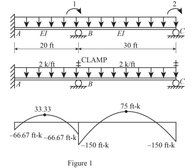
Analysis of the restrained structure:
The rotation at joint B and C are restrained by a clamp.
Calculate the fixed end moments as shown below.
For member AB:
For member BC:
Sketch the details of the beam, fixed end moments in restrained structure produced by applied loads, the clamp applied, and the moment diagrams in restrained structure as shown in Figure 1.
Sketch the free body diagram of joint as shown in Figure 2.
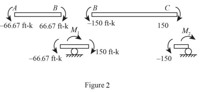
Refer to Figure 2.
Calculate the restraining moments as shown below.
At joint B:
At joint B:
Provide the restraining force vector as shown below.
The elements in the restraining force vectors is the value of restraining moments with its sign reversed.
Assembly of the structure stiffness matrix:
Sketch the Free Body Diagram of the unit rotation at B as shown in Figure 3.
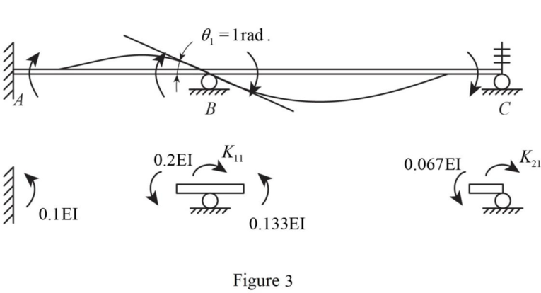
Refer to Figure 3.
Introduce a unit rotation at joint B.
Calculate the end moments of members AB and BC as shown below.
For member AB:
For member BC:
The stiffness matrix for joint B and C due to the unit rotation at B is
Introduce a unit rotation at joint C.
Sketch the Free Body Diagram of the unit rotation at C as shown in Figure 4.
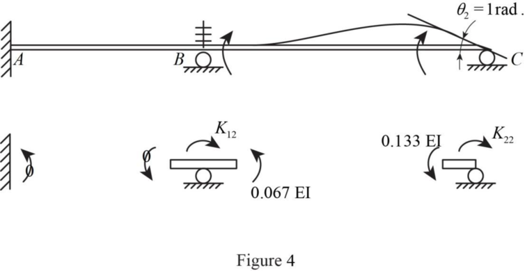
Refer to Figure 4.
Calculate the end moments of members AB and BC as shown below.
For member AB:
For member BC:
The stiffness matrix for joint B and C due to the unit rotation at C is
Provide the stiffness matrix of the beam as shown below.
Calculate the unknown joint displacements as shown below.
Evaluation of the effects of joint displacements:
Calculate the final moment of the spans due to the unit rotation as shown below.
For span AB:
For span BC.
Sketch the Free Body Diagram of span AB and BC as shown in Figure 5.
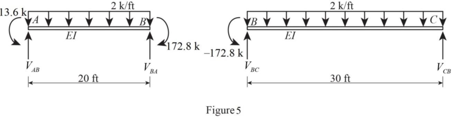
Refer to Figure 5.
Consider span AB.
Use equilibrium equations:
Summation of moments about A is equal to 0.
Summation of forces along y-direction is equal to 0.
Consider span BC.
Use equilibrium equations:
Summation of moments about B is equal to 0.
Summation of forces along y-direction is equal to 0.
The reaction at support B.
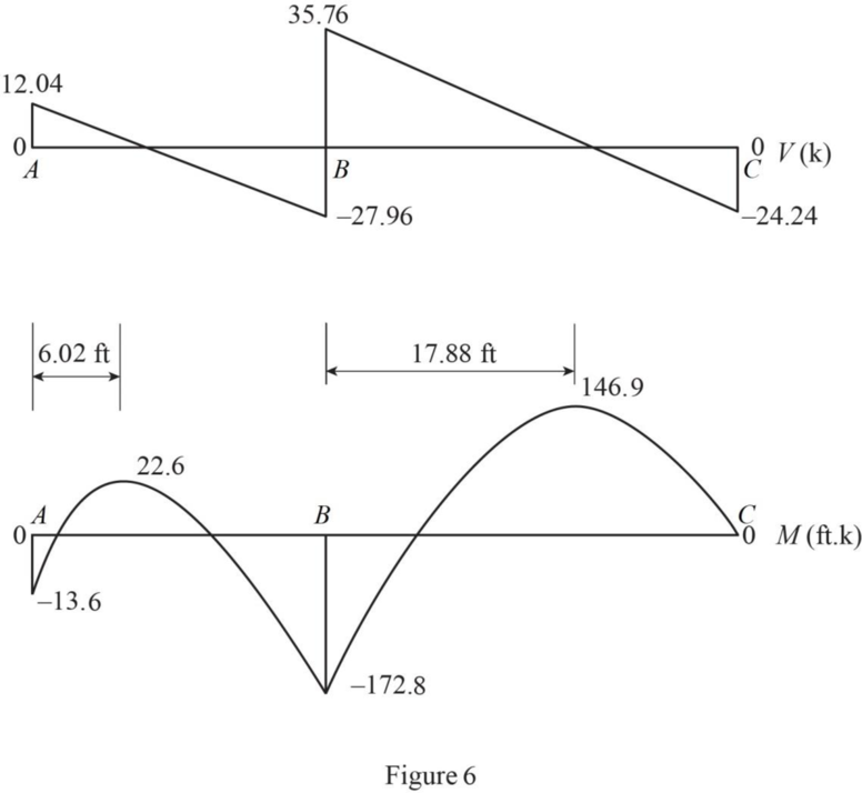
Calculate the shear at each point of the beam as shown below.
Calculate the point of zero shear as shown below.
Consider a section at a distance x from A in span AB.
Consider a section at a distance x from B in span BC.
Calculate the moment at each point of the beam as shown below.
Sketch the shear and moment diagram for the beam as shown in Figure 6.
Want to see more full solutions like this?
Chapter 16 Solutions
Fundamentals of Structural Analysis


 Structural Analysis (10th Edition)Civil EngineeringISBN:9780134610672Author:Russell C. HibbelerPublisher:PEARSON
 Principles of Foundation Engineering (MindTap Cou...Civil EngineeringISBN:9781337705028Author:Braja M. Das, Nagaratnam SivakuganPublisher:Cengage Learning
 Fundamentals of Structural AnalysisCivil EngineeringISBN:9780073398006Author:Kenneth M. Leet Emeritus, Chia-Ming Uang, Joel LanningPublisher:McGraw-Hill Education
 Traffic and Highway EngineeringCivil EngineeringISBN:9781305156241Author:Garber, Nicholas J.Publisher:Cengage Learning