
Concept explainers
Videos
Find the total impedance of the parallel networks of Fig. 1663 in rectangular and polar form.
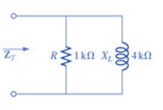
Fig. 1663
(a)
Total impedance of the given network.
Answer to Problem 1P
Rectangular form:
Polar form:
Explanation of Solution
Given:
The given network is:
Calculation:
We can see from the given circuit that the resistor
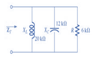
(b)
Total impedance of the given network.
Answer to Problem 1P
Rectangular form:
Polar form:
Explanation of Solution
Given:
The given network is:
Calculation:
We can see from the given circuit that the resistor
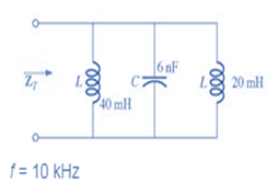
(c)
Total impedance of the given network.
Answer to Problem 1P
Rectangular form:
Polar form:
Explanation of Solution
Given:
The given network is:
Calculation:
We can see from the given circuit that two inductors and one capacitor are connected in parallel.
Therefore, we need to calculate their equivalent reactance first:
Inductive reactance of
Inductive reactance of
Capacitive reactance of
Therefore, the total resistance of the network will be:
Want to see more full solutions like this?
Chapter 16 Solutions
Laboratory Manual for Introductory Circuit Analysis
Additional Engineering Textbook Solutions
Engineering Electromagnetics
Principles and Applications of Electrical Engineering
Electric Circuits. (11th Edition)
Electric machinery fundamentals
Fundamentals of Applied Electromagnetics (7th Edition)
Programmable Logic Controllers


- Find a state space model for the following electrical network. Let the output of the system be y(t).arrow_forwardFor the network of Fig. 1: i) Draw the re model equivalent circuit. ii) Calculate IB, IC, and re. iii) Determine Zi and Z0. Here Vcc = 12Varrow_forwardDetermine Vo for the network shown. Kindly show complete solution so that I can understand.arrow_forward
- Find Rab in the given network. Show complete solution.arrow_forwardA room 15 m x 15 m is lit by 20 lamps to a fairly uniform illumination of 100 lm/m2. Calculate the utilization coefficient of the room given that the output of each lamp is 1600 lumens.arrow_forwardUse mesh analysis to find the voltage Vo.arrow_forward
- Using nodal analysis obtain V in the circuitarrow_forwardthe following electrical circuit questions 1. Check the Reciprocity theorem for the network, with source and output response positions being at input and output terminals. 2.Draw an oriented graph for the network and obtain the corresponding incidence matrix. Then, find all cut sets and loops of the network. 3.For the network, assign arbitrary branch voltages and branch currents subject only to KVL and KCL constraints. Then, verify the conclusion of Tellegen’s theorem.arrow_forwardSeries RL Circuit Given if E = 20v / 10khz, R1 = 5kW, C =10mh Find Z, I,Vr, VLarrow_forward
 Introductory Circuit Analysis (13th Edition)Electrical EngineeringISBN:9780133923605Author:Robert L. BoylestadPublisher:PEARSON
 Delmar's Standard Textbook Of ElectricityElectrical EngineeringISBN:9781337900348Author:Stephen L. HermanPublisher:Cengage Learning
 Programmable Logic ControllersElectrical EngineeringISBN:9780073373843Author:Frank D. PetruzellaPublisher:McGraw-Hill Education
 Fundamentals of Electric CircuitsElectrical EngineeringISBN:9780078028229Author:Charles K Alexander, Matthew SadikuPublisher:McGraw-Hill Education
 Electric Circuits. (11th Edition)Electrical EngineeringISBN:9780134746968Author:James W. Nilsson, Susan RiedelPublisher:PEARSON
 Engineering ElectromagneticsElectrical EngineeringISBN:9780078028151Author:Hayt, William H. (william Hart), Jr, BUCK, John A.Publisher:Mcgraw-hill Education,