
Videos
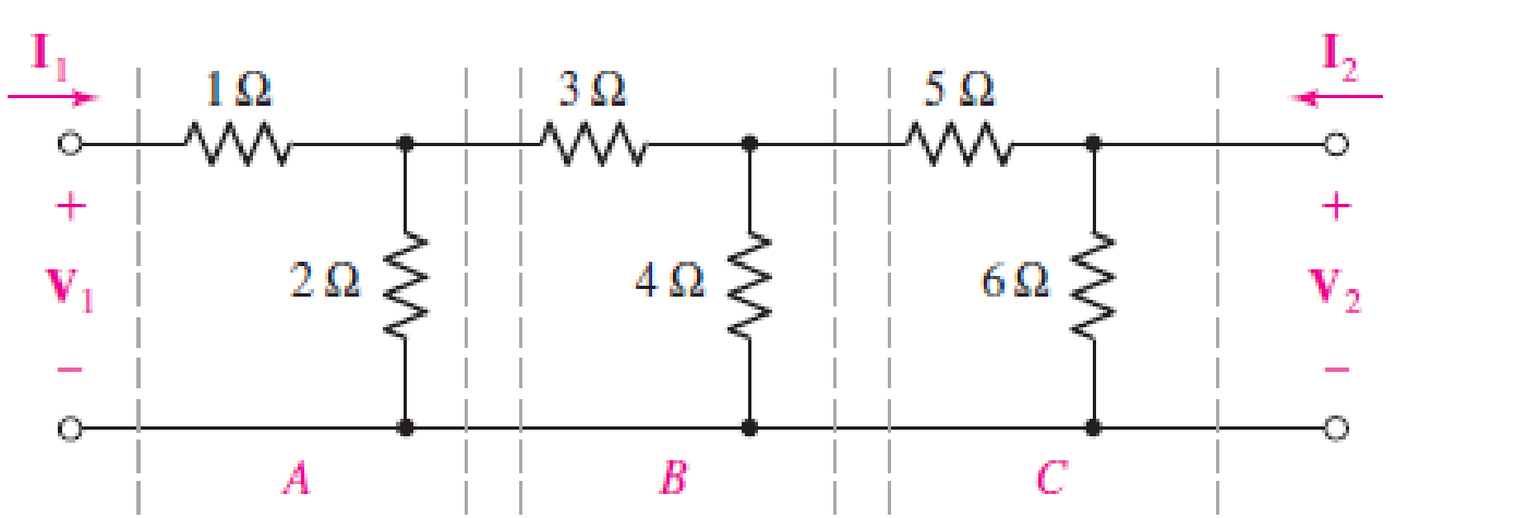
The two-port of Fig. 16.65 can be viewed as three separate cascaded two-ports A, B, and C. (a) Compute t for each network. (b) Obtain t for the cascaded network. (c) Verify your answer by naming the two middle nodes Vx and Vy, respectively, writing nodal equations, obtaining the admittance parameters from your nodal equations, and converting to t parameters using Table 16.1.
(a)
The
Answer to Problem 54E
The
Explanation of Solution
Calculation:
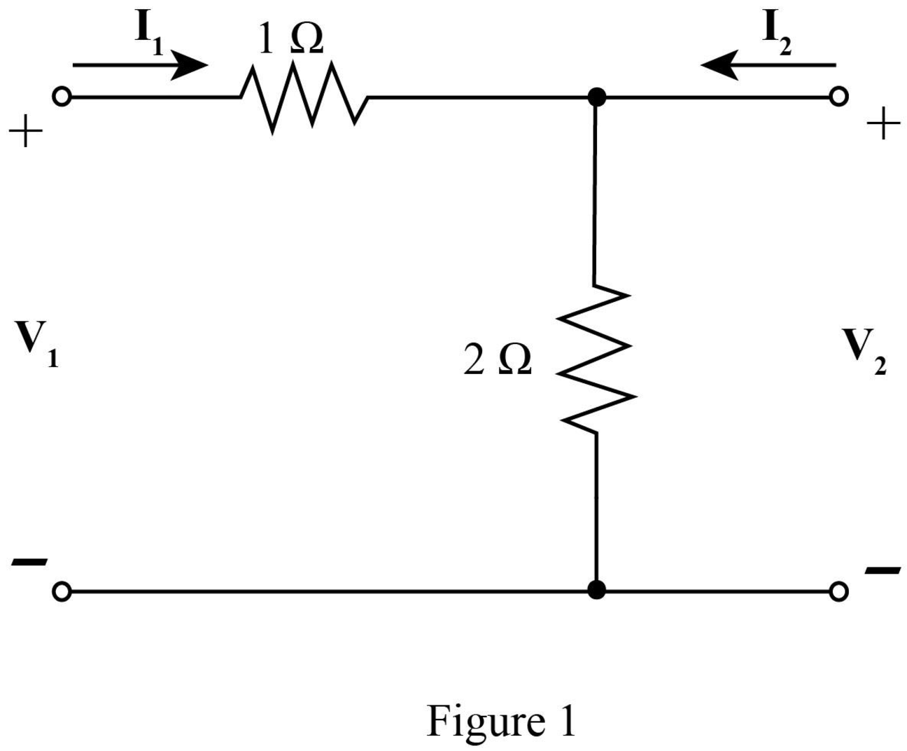
The required diagram is shown in Figure 1.
Here,
The mesh equation from the input side is given by,
The mesh equations at the output side is given by,
Substitute
The
Here,
Write equations (6) and (7) in matrix form.
Compare equation (3) with equation (4).
Compare equation (2) with equation (6).
The
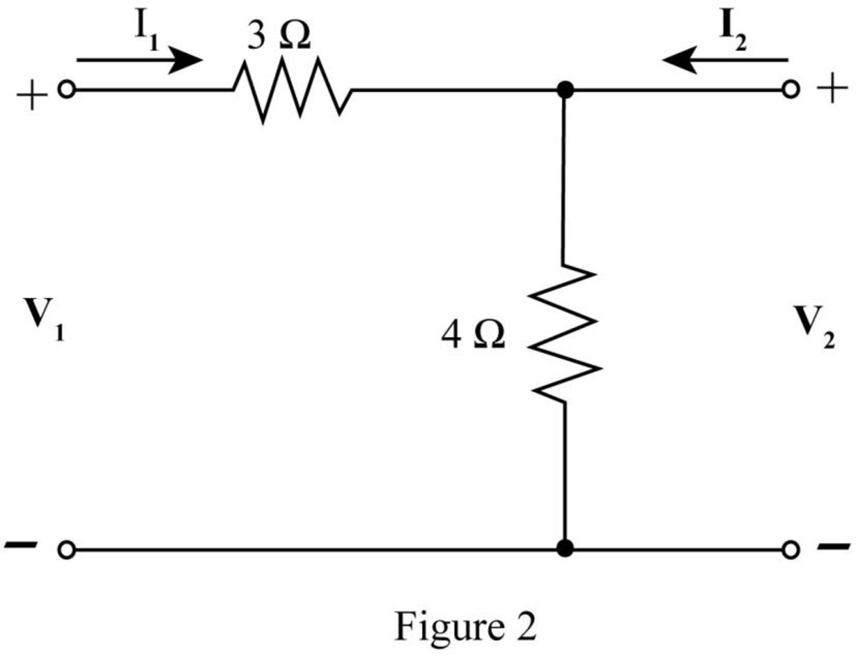
The required diagram is shown in Figure 2.
The mesh equation from the input side is given by,
The mesh equations at the output side is given by,
Substitute
Compare equation (8) with equation (4).
Compare equation (7) with equation (5).
The
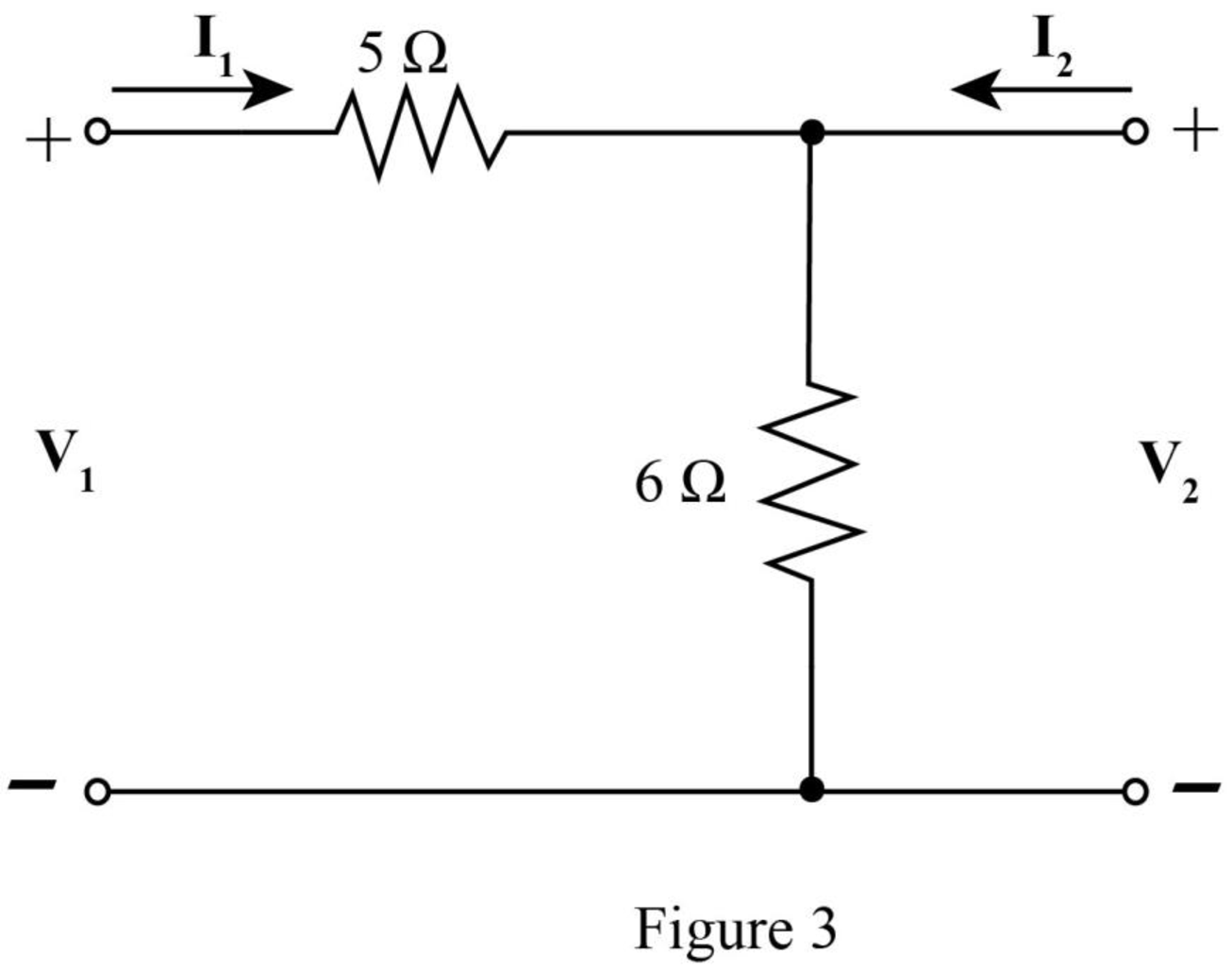
The required diagram is shown in Figure 3.
The mesh equation from the input side is given by,
The mesh equations at the output side is given by,
Substitute
Compare equation (11) with equation (4).
Compare equation (10) with equation (5).
The
Conclusion:
Therefore, the
(b)
The
Answer to Problem 54E
The
Explanation of Solution
Calculation:
The
Substitute
Conclusion:
Therefore, the
(c)
To verify: The above answers by obtaining the admittance parameter and converting them to
Answer to Problem 54E
The values have been verified.
Explanation of Solution
Calculation:
The required diagram is shown in Figure 4.
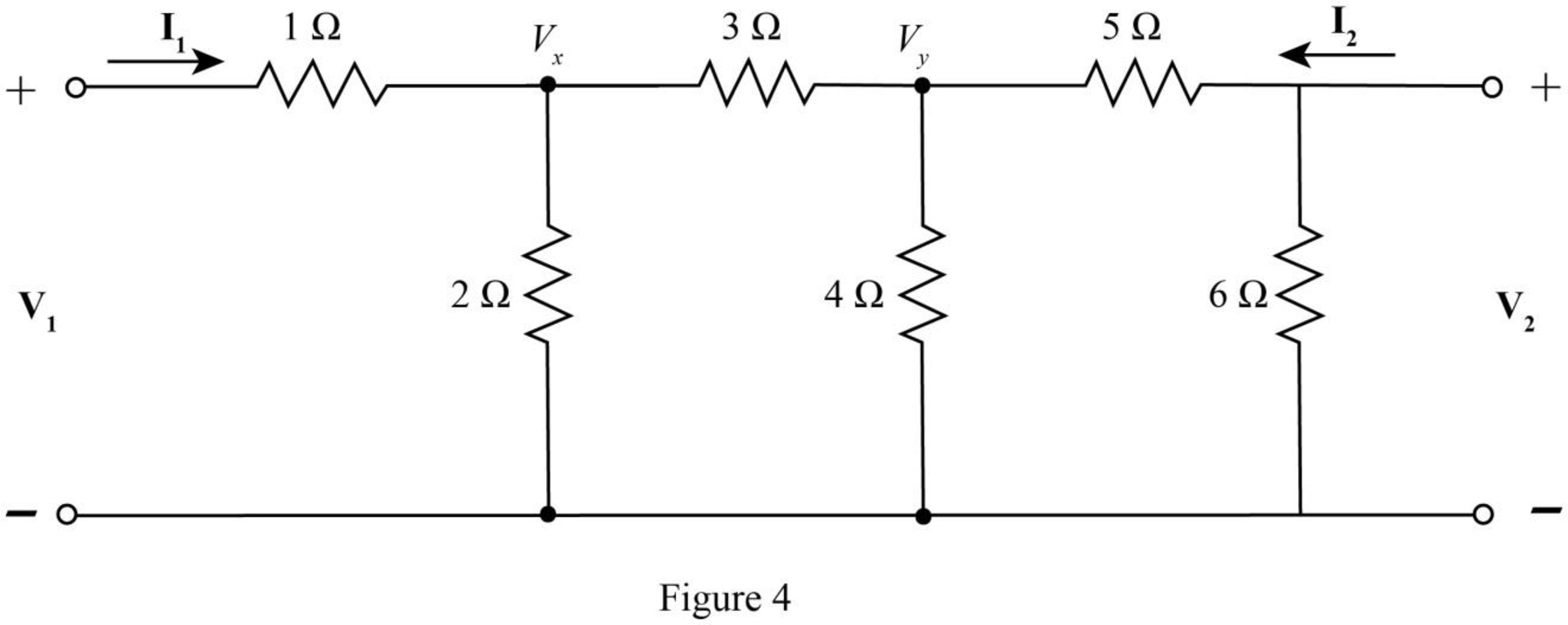
The nodal equation at node
The nodal equations at node
Substitute
Substitute
The current
Substitute
The current
Substitute
The
Here,
Compare equation (16) with equation (18).
Compare equation (17) with equation (19).
The determinant of the matrix
Substitute
The relation between
Substitute
Within the limits of error, the values have been verified.
Conclusion:
Therefore, the values have been verified.
Want to see more full solutions like this?
Chapter 16 Solutions
Loose Leaf for Engineering Circuit Analysis Format: Loose-leaf
Additional Engineering Textbook Solutions
Electrical Engineering: Principles & Applications (7th Edition)
Engineering Electromagnetics
Fundamentals of Applied Electromagnetics (7th Edition)
Principles Of Electric Circuits
ANALYSIS+DESIGN OF LINEAR CIRCUITS(LL)
Fundamentals of Electric Circuits


- A two-port is described by the following equations: V1 = 50I1 + 10I2 and V2 = 30I1 + 20I2. Which of the following is not true? Z12 = 10 Y12 = -0.0143 h12 = 0.5 B = 50arrow_forwardCompute the convolution y(n) = x(n) * h(n), Where x(n) = {1,1,0,1,1} and h(n) = {1,-2,-3,4), Using Tabulation method.arrow_forward26 - Which of the following is true regarding Synchronous Circuits? a) O Updates are fast because they depend on instantaneous and individual propagation delays. b) O Power consumption is low. c) O Updates are common and must take longer than the slowest propagation delay available. Therefore, they are slow. d) Because memory elements are updated at different times, their design and analysis are difficult.arrow_forward
- Determine (draw) a two-port network that is represented by the following z parameters.arrow_forwardData Communication Suppose that Ali’s and Paul’s computers are connected by an 8 Kbps link (note, 1 Kbps = 103 bps) that uses circuit switching and that Ali sent some number of bits to Paul over the link. Suppose that circuit switching on the link connecting Ali’s and Paul’s computers is implemented using Time Division Multiplexing (TDM), that a frame is 1 sec in duration, and that a frame consists of 16 slots. Ali is assigned one slot in every frame. Considering that it took 12 minutes for Ali to send all bits to Paul, find how many bits were sent by Ali to Paul.arrow_forwardNote: Please write clear and answer neatly with solutions, thank you! Find the T-parameters of a two-port device whose Z-parameters are Z11 = s, Z12 = Z21 =10s, and Z22 = 100s.arrow_forward
- A combinational circuit has four inputs (A, B, C, D) and three outputs (X, Y, Z). XYZ represents a binary number whose value equals the number of 1’s at the input. For example if ABCD = 1011, XYZ = 011.(Step by step) 1,Construct a truth table for this circuit in terms of its inputs and outputs. 2,Find the minterm expansions for X and Y. 3,Find the maxterm expansion for Z.arrow_forwardSuppose two hosts, A and B, are separated by 20,000 kilometers and are connected by a direct link of R=2R=2 Mbps. Suppose the propagation speed over the link is 2.5⋅1082.5⋅108 meters/sec. Calculate the bandwidth-delay product, R⋅dpropR⋅dprop. Consider sending a file of 800,000 bits from Host A to Host B. Suppose the file is sent continuously as one large message. What is the maximum number of bits that will be in the link at any given time? Provide an interpretation of the bandwidth-delay product. What is the width (in meters) of a bit in the link? Is it longer than a football field? Derive a general expression for the width of a bit in terms of the propagation speed s, the transmission rate R, and the length of the link m.arrow_forwardA compact disc (CD) recording system samples each of two stereo signals witha 16-bit AD-converter at 44.1 kilosamples/s. 4. The CD can record an hour’s worth of music. Determine the number ofbits recorded on a CD. 5. For a comparison, a good collegiate dictionary may contain 1500 pages,2 columns/page, 100 lines/column, 7 words/line, 6 letters/word, and 6bits/letter. Determine the number of bits required to describe the dictionary and estimate the number of comparable books that can be stored ona CD.arrow_forward
 Introductory Circuit Analysis (13th Edition)Electrical EngineeringISBN:9780133923605Author:Robert L. BoylestadPublisher:PEARSON
 Delmar's Standard Textbook Of ElectricityElectrical EngineeringISBN:9781337900348Author:Stephen L. HermanPublisher:Cengage Learning
 Programmable Logic ControllersElectrical EngineeringISBN:9780073373843Author:Frank D. PetruzellaPublisher:McGraw-Hill Education
 Fundamentals of Electric CircuitsElectrical EngineeringISBN:9780078028229Author:Charles K Alexander, Matthew SadikuPublisher:McGraw-Hill Education
 Electric Circuits. (11th Edition)Electrical EngineeringISBN:9780134746968Author:James W. Nilsson, Susan RiedelPublisher:PEARSON
 Engineering ElectromagneticsElectrical EngineeringISBN:9780078028151Author:Hayt, William H. (william Hart), Jr, BUCK, John A.Publisher:Mcgraw-hill Education,