
Concept explainers
Videos
The coefficients of friction between the 30-lb block and the 5-lb platform BD are μs = 0.50 and μk = 0.40. Determine the accelerations of the block and of the platform immediately after wire AB has been cut.
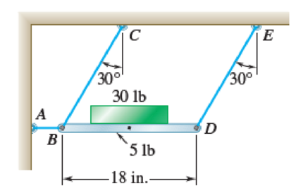
Fig. P16.20
Calculate the accelerations of the block and of the platform immediately after wire AB has been cut
Answer to Problem 16.20P
The accelerations of the block and of the platform immediately after wire AB has been cut
Explanation of Solution
Given information:
The weight of the block
The weight of the platform BD
The coefficients of static friction
The coefficients of kinetic friction
The length of the platform BD (L) is
Calculation:
Consider the acceleration due to gravity (g) is
Consider the block does not slide relative to the platform.
Show the free body and kinetic diagram of the platform and block as in Figure 1.
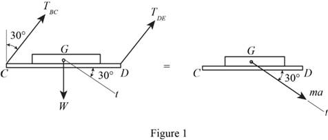
Here,
Refer to Figure 1.
Calculate the forces at the tangent:
Substitute
Calculate the acceleration of the block and of the platform (a):
Substitute and
Check whether or not the block will slide relative to the platform.
Show the free body and kinetic diagram of the block as in Figure 2.
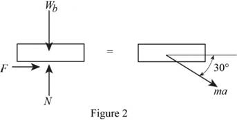
Here, F is the horizontal force of the block and N is the vertical force of the block.
Refer to Figure 2
Calculate the horizontal forces by applying the equation of equilibrium:
Substitute
Substitute
Calculate the vertical forces by applying the equation of equilibrium:
Substitute
Substitute
Calculate the force of the block
Substitute 0.50 for
Since, the block will slide.
Consider the block slides relative to the platform.
Calculate the Equations of motion for block:
Show the free body and kinetic diagram of the block as in Figure 3.
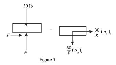
Here,
Refer to Figure 3
Calculate the vertical forces by applying the equation of equilibrium:
Calculate the horizontal forces by applying the equation of equilibrium:
Substitute
Substitute 0.40 for
Calculate the Equations of motion for platform:
Show the free body and kinetic diagram of the platform as in Figure 4.
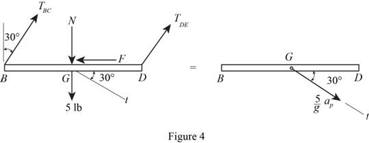
Here,
Refer to Figure 4
Calculate the forces at the tangent:
Substitute
If contact is maintained between block and platform.
Therefore,
Calculate the vertical force of the block (N):
Substitute
Calculate the acceleration of the block at x direction
Substitute
Calculate the acceleration of the block at y direction
Substitute
Calculate the accelerations of the block
Substitute
Calculate the angle of the block
Substitute
Calculate the accelerations of the platform
Substitute
Calculate the angle of the platform
Substitute
Hence, the accelerations of the block and of the platform immediately after wire AB has been cut
Want to see more full solutions like this?
Chapter 16 Solutions
Vector Mechanics for Engineers: Statics and Dynamics
Additional Engineering Textbook Solutions
DESIGN OF MACHINERY
Heat and Mass Transfer: Fundamentals and Applications
Degarmo's Materials And Processes In Manufacturing
Thermodynamics: An Engineering Approach
Statics and Mechanics of Materials (5th Edition)
Engineering Mechanics: Statics


- The mechanism shown is one of two identical mechanisms attached to the two sides of a 200-lb uniform rectangular door. Edge ABC of the door is guided by wheels of negligible mass that roll in horizontal and vertical tracks. A spring with a constant k is attached to wheel B in such a way that its tension is zero when 0 = 30°, Knowing that the door is released from rest in the position 0 = 45° and reaches the vertical position with an angular velocity of 0.6 rad/s, determine the spring constant k.arrow_forwardA 48-kg advertising panel of length 2a = 2.4 m and width 2b = 1.6 m is kept rotating at a constant rate w1 about its horizontal axis by a small electric motor attached at A to frame ACB. This frame itself is kept rotating at a constant rate w2 about a vertical axis by a second motor attached at C to the column CD. Knowing that the panel and the frame complete a full revolution in 6 s and 12 s, respectively, express, as a function of the angle 0, the dynamic reaction exerted on column CD by its support at D.arrow_forwardA small 250-g collar C can slide on a semicircular rod which is made to rotate about the vertical AB at a constant rate of 7.5 rad/s. Determine the three values of 0 for which the collar will not slide on the rod, assuming no friction between the collar and the rod.arrow_forward
- 1 A 6-ft board is placed in a truck with one end resting against a block secured to the floor and the other leaning against a vertical partition. Draw the FBD and KD necessary to determine the maximum allowable acceleration of the truck if the board is to remain in the position shown.arrow_forwardGreek engineers had the unenviable task of moving large columns from the quarries to the city. One engineer, Chersiphron, tried several different techniques to do this. One method was to cut pivot holes into the ends of the stone and then use oxen to pull the column. The 4-ft diameter column weighs 12,000 lbs, and the team of oxen generates a constant pull force of 1500 lbs on the center of the cylinder G. Knowing that the column starts from rest and rolls without slipping, determine (a) the velocity of its center G after it has moved 5 ft, (b) the minimum static coefficient of friction that will keep it from slipping.arrow_forwardA small 250-g collar C can slide on a semicircular rod which is made to rotate about the vertical AB at a constant rate of 7.5 rad/s. Knowing that the coefficients of friction are μs = 0.25 and μk = 0.20, indicate whether the collar will slide on the rod if it is released in the position corresponding to (a) 0= 75°, (b) 0 = 40°. Also, determine the magnitude and direction of the friction force exerted on the collar immediately after release.arrow_forward
- Two identical giant flywheels are on 2 identical slopes at an angle alpha = 20 deg. One flywheel is rolling on its inside shaft of diameter d1 = 3 ft, and the second flywheel is rolling without slipping on its outside diameter d2 = 5 ft. They are both released from rest. The weight of the flywheel is W = 8 lbs Knowing that flywheel 1 attains a speed of v = 7.0 ft/s in t = [t] s, (if t doesn't show take any t between 5 and 10 sec) find the radius of gyration of the flywheels, following those steps: b. Find omega final c. Find the angular impulse at the point of contact between the shaft and the slope. d. Write the formula to find the final momentum. e. Solve for k, using the principle of angular impulse and momentumarrow_forwardBoxes A and B are at rest on a conveyor belt that is initially at rest. The belt is suddenly started in an upward direction so that slipping occurs between the belt and the boxes. Knowing that the coefficients of kinetic friction between the belt and the boxes are (μk) A= 0.30 and (μk)B= 0.32, determine the initial acceleration of each box.arrow_forwardA bowler projects an 8-in.-diameter ball weighing 12 lb along an alley with a forward velocity v0 of 15 ft/s and a backspin ω0 of 9 rad/s. Knowing that the coefficient of kinetic friction between the ball and the alley is 0.10, determine (a) the time t1 at which the ball will start rolling without sliding, (b) the speed of the ball at time t1, (c) the distance the ball will have traveled at time t1arrow_forward
- Two identical giant flywheels are on 2 identical slopes at an angle alpha = 20 deg. One flywheel is rolling on its inside shaft of diameter d1 = 3 ft, and the second flywheel is rolling without slipping on its outside diameter d2 = 5 ft. They are both released from rest. The weight of the flywheel is W = 8 lbs 1. Knowing that flywheel 1 attains a speed of v = 7.0 ft/s in t = [t] s, (if t doesn't show take any t between 5 and 10 sec) find the radius of gyration of the flywheels, following those steps: 3. What will be the distance between the 2 flywheels? Which one is in front? a. Explain your strategy to find the distance made by each wheel. b. Find the 3 distances made by each wheel. c. Find the distance between the 2 flywheels. d. Why one is in front? 4. Using flywheel 2, what is the coefficient of static friction between the outside diameter and the ground required to prevent slipping? a. Using the 3 previous diagrams, which impulse will you consider finding the force of…arrow_forwardA 12-lb block B rests as shown on the upper surface of a 30-lb wedge A. Neglecting friction, determine immediately after the system is released from rest (a) the acceleration of A, (b) the acceleration of B relative to A.arrow_forwardKnowing that the coefficients of friction between the component I and member BC of the mechanism of Prob. 12.62 are μk = 0.35 and = 0.25, determine (μk a) the maximum allowable constant speed VB if the component is not to slide on BC while being transferred, (b) the values of 0 for which sliding is impending.Reference to Problem 12.62:arrow_forward
 Elements Of ElectromagneticsMechanical EngineeringISBN:9780190698614Author:Sadiku, Matthew N. O.Publisher:Oxford University Press
 Mechanics of Materials (10th Edition)Mechanical EngineeringISBN:9780134319650Author:Russell C. HibbelerPublisher:PEARSON
 Thermodynamics: An Engineering ApproachMechanical EngineeringISBN:9781259822674Author:Yunus A. Cengel Dr., Michael A. BolesPublisher:McGraw-Hill Education
 Control Systems EngineeringMechanical EngineeringISBN:9781118170519Author:Norman S. NisePublisher:WILEY
 Mechanics of Materials (MindTap Course List)Mechanical EngineeringISBN:9781337093347Author:Barry J. Goodno, James M. GerePublisher:Cengage Learning
 Engineering Mechanics: StaticsMechanical EngineeringISBN:9781118807330Author:James L. Meriam, L. G. Kraige, J. N. BoltonPublisher:WILEY