
Videos
Disk B is at rest when it is brought into contact with disk A, which has an initial angular velocity ω0. (a) Show that the final angular velocities of the disks are independent of the coefficient of friction μk between the disks as long as μk ≠ 0. (b) Express the final angular velocity of disk A in terms of ω0 and the ratio of the masses of the two disks, mA/mB.
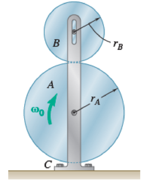
Fig. P16.43 and P16.44
(a)
Show that the final velocities of disk A and B are independent of coefficient of kinetic friction
Explanation of Solution
The mass of the disk A is
The mass of the disk B is
The initial angular velocity of the disk A is
The coefficient of the kinetic friction is
The radius of the disk A is
The radius of the disk B is
The acceleration due to gravity is g.
The time required for the disk to come to rest is t.
Calculation:
Calculate the mass moment of inertia of the disk A
Calculate the mass moment of inertia of the disk B
Calculate the load of the disk A
Calculate the load of the disk B
Show the free body diagram of the disk B as in Figure 1.
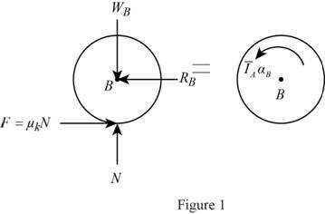
Here,
Refer to Figure 1.
Calculate the vertical forces by applying the equation of equilibrium:
Sum of vertical forces is equal to 0.
Substitute
Calculate the magnitude of the friction force
Substitute
Calculate the horizontal forces by applying the equation of equilibrium:
Sum of horizontal forces is equal to 0.
Substitute
Calculate the angular acceleration of the disk B
Calculate the moment about point B by applying the equation of equilibrium:
Substitute
Show the free body diagram of the disk A as in Figure 2.
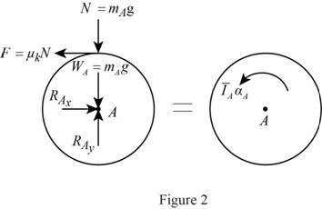
Here,
Refer to Figure 2.
Calculate the horizontal forces by applying the equation of equilibrium:
Sum of horizontal forces is equal to 0.
Substitute
Calculate the vertical forces by applying the equation of equilibrium:
Sum of vertical forces is equal to 0.
Substitute
Calculate the angular acceleration of the disk A
Calculate the moment about point A by applying the equation of equilibrium:
Substitute
The angular velocity of the disk A
Substitute
The angular velocity of the disk B
Substitute
While there is no slipping between disk A and B, their velocity ratio is same.
Show the free body diagram of the system as in Figure 3.
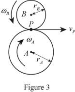
Refer to Figure 3.
The velocity of pinion
Substitute
Calculate the angular velocity of the disk A
Substitute
Calculate the angular velocity of the disk B
Substitute
From Equation (5) and (6), it is clear that the final velocities of disk A and B are independent of coefficient of kinetic friction
(b)
Express the final angular velocity of disk A in terms of
Answer to Problem 16.44P
The final angular velocity of disk A in terms of
Explanation of Solution
The mass of the disk A is
The mass of the disk B is
The initial angular velocity of the disk A is
The coefficient of the kinetic friction is
The radius of the disk A is
The radius of the disk B is
The acceleration due to gravity is g.
The time required for the disk to come to rest is t.
Calculation:
Refer to part (a).
Calculate the final angular velocity of disk A in terms of
Refer Equation (5).
Hence, the final angular velocity of disk A in terms of
Want to see more full solutions like this?
Chapter 16 Solutions
Vector Mechanics for Engineers: Statics and Dynamics
Additional Engineering Textbook Solutions
Machine Tool Practices (10th Edition)
Vector Mechanics for Engineers: Statics
Vector Mechanics for Engineers: Statics, 11th Edition
DeGarmo's Materials and Processes in Manufacturing
Thermodynamics: An Engineering Approach
Automotive Technology: Principles, Diagnosis, And Service (6th Edition) (halderman Automotive Series)


- The 10-in.-radius brake drum is attached to a larger flywheel which is not shown. The total mass moment of inertia of the flywheel and drum is 22 lb ⋅ ft ⋅ s 2 and the coefficient of kinetic friction between the drum and the brake shoe is 0.41. Knowing that the initial angular velocity is 255 rpm clockwise, determine the force which must be exerted by the hydraulic cylinder at point B if the system is to stop in 85 revolutions. determine the force which must be exerted by the hydraulic cylinder at point B if the system is to stop in 85 revolutions. DO NOT ROUND OFF IN THE SOLUTION. ROUND OFF ONLY IN 2 DECIMAL PLACE IN THE FINAL ANSWER.arrow_forwardThe 8-in. radius brake drum is attached to a larger flywheel that is not shown. The total mass moment of inertia of the drum and the flywheel is 15 lb.ft.s2 and the coefficient of kinetic friction between the drum and the brake shoe is 0.40. Knowing that the angular velocity of the flywheel is 450 rpm clockwise when a force P of magnitude 65 lbf. is applied to the pedal C, determine the number of the revolutions executed by the flywheel before it comes to rest. (The final answer should be in two decimal places with correct units)arrow_forwardA wheel of radius r and centroidal radius of gyration k is released from rest on the incline shown at time t = 0. Assuming that the wheel rolls without sliding, determine (a) the velocity of its center at time t, (b) the coefficient of static friction required to prevent slipping.arrow_forward
- A 3-kg bar AB is attached by a pin at D to a 4-kg square plate, which can rotate freely about a vertical axis. Knowing that the angular velocity of the plate is 120 rpm when the bar is vertical, determine (a ) the angular velocity of the plate after the bar has swung into a horizontal position and has come to rest against pin C, (b) the energy lost during the plastic impact at C.arrow_forwardA long ladder of length l, mass m, and centroidal mass moment of inertia I is placed against a house at an angle 0=0O. Knowing that the ladder is released from rest, determine the angular velocity of the ladder when 0=02. Assume the ladder can slide freely on the horizontal ground and on the vertical wall.arrow_forwardA 1200-kg satellite designed to study the sun has an angular velocity of w0 = (0.050 rad/s)i + (0.075 rad/s)k when two small jets are activated at A and B in a direction parallel to the y axis. Knowing that the coordinate axes are principal centroidal axes, that the radii of gyration of the satellite are and that each jet produces a 50-N thrust, determine (a ) the required operating time of each jet if the angular velocity of the satellite is to be reduced to zero, (b ) the resulting change in the velocity of the mass center G.arrow_forward
- Each of the gears A and B has a mass of 675 g and a radius of gyration of 40 mm, while gear C has a mass of 3.6 kg and a radius of gyration of 100 mm. Assume that kinetic friction in the bearings of gears A, B C produces couples of constant magnitude 0.15 N.m, 0.15 N.m, 0.3 N.m, respectively. Knowing that the initial angular velocity of gear C is 2000 rpm, determine the time required for the system to come to rest.arrow_forwardThe uniform 4-kg cylinder A with a radius of r = 150 mm has an angular velocity of w0 = 50 rad/s when it is brought into contact with an identical cylinder B that is at rest. The coefficient of kinetic friction at the contact point D is μk. After a period of slipping, the cylinders attain constant angular velocities of equal magnitude and opposite direction at the same time. Knowing that cylinder A executes three revolutions before it attains a constant angular velocity and cylinder B executes one revolution before it attains a constant angular velocity, determine (a) the final angular velocity of each cylinder, (b) the coefficient of kinetic friction μk.arrow_forwardThe double pulley shown has a mass of 15 kg and a centroidal radius of gyration of 160 mm. Cylinder A and block B are attached to cords that are wrapped on the pulleys as shown. The coefficient of kinetic friction between block and the surface is 0.2. Knowing that the system is at rest in the position shown when a constant force P = 200 N is applied to cylinder A , determine (a ) the velocity of cylinder A as it strikes the ground, (b ) the total distance that block B moves before coming to rest.arrow_forward
- The rotor of an electric motor has an angular velocity of 3600 rpm when the load and power are cut off. The 110-lb rotor, which has a centroidal radius of gyration of 9 in., then coasts to rest. Knowing that the kinetic friction of the rotor produces a couple with a magnitude of 2.5 1b.ft determine the number of revolutions that the rotor executes before coming to rest.arrow_forwardThe rotor of an electric motor has an angular velocity of 3600 rpm when the load and power are cut off. The 120-lb rotor, which has a centroidal radius of gyration of 9 in., then coasts to rest. Knowing that kinetic friction results in a couple of magnitude 2.5 lb·ft exerted on the rotor, determine the number of revolutions that the rotor executes before coming to rest.arrow_forwardThe mechanism shown is one of two identical mechanisms attached to the two sides of a 200-lb uniform rectangular door. Edge ABC of the door is guided by wheels of negligible mass that roll in horizontal and vertical tracks. A spring with a constant k is attached to wheel B in such a way that its tension is zero when 0 = 30°, Knowing that the door is released from rest in the position 0 = 45° and reaches the vertical position with an angular velocity of 0.6 rad/s, determine the spring constant k.arrow_forward
 Elements Of ElectromagneticsMechanical EngineeringISBN:9780190698614Author:Sadiku, Matthew N. O.Publisher:Oxford University Press
 Mechanics of Materials (10th Edition)Mechanical EngineeringISBN:9780134319650Author:Russell C. HibbelerPublisher:PEARSON
 Thermodynamics: An Engineering ApproachMechanical EngineeringISBN:9781259822674Author:Yunus A. Cengel Dr., Michael A. BolesPublisher:McGraw-Hill Education
 Control Systems EngineeringMechanical EngineeringISBN:9781118170519Author:Norman S. NisePublisher:WILEY
 Mechanics of Materials (MindTap Course List)Mechanical EngineeringISBN:9781337093347Author:Barry J. Goodno, James M. GerePublisher:Cengage Learning
 Engineering Mechanics: StaticsMechanical EngineeringISBN:9781118807330Author:James L. Meriam, L. G. Kraige, J. N. BoltonPublisher:WILEY