
Concept explainers
Videos
(a)
Find the angular acceleration of each cylinder
(a)
Answer to Problem 16.45P
The angular acceleration of each cylinder
Explanation of Solution
The weight of the cylinder A
The weight of the cylinder B
The weight of the cylinder C
The initial angular velocity of the cylinder A
The coefficient of the kinetic friction
The radius of the cylinder A
The radius of the cylinder B
The radius of the cylinder C
Calculation:
Consider the acceleration due to gravity (g) as
Convert the unit of the radius of the cylinder A
Convert the unit of the radius of the cylinder B
Convert the unit of the radius of the cylinder C
Calculate the mass of the cylinder A
Substitute
Calculate the mass of the cylinder B
Substitute
Calculate the mass of the cylinder C
Substitute
Calculate the mass moment of inertia of the cylinder A
Substitute
Calculate the mass moment of inertia of the cylinder B
Substitute
Calculate the mass moment of inertia of the cylinder C
Substitute
Calculate the tangential acceleration of contact point between cylinder B and C
Here,
The friction force at the contact point between cylinder A and C
Show the free body diagram of the cylinder B as in Figure 1.
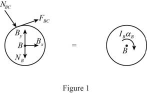
Here,
Refer to Figure 1.
Calculate the moment about point B by applying the equation of equilibrium:
Substitute
Show the free body diagram of the cylinder C as in Figure 2.
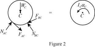
Here,
Refer to Figure 2.
Calculate the moment about point C by applying the equation of equilibrium:
Substitute
Calculate the normal force at the contact point between cylinder A and C
Substitute
Consider that the contact point between cylinder A and C is P.
Calculate the components of forces acting along the line CP:
Calculate the angular acceleration of the cylinder C
Substitute
Calculate the friction force at the contact point between cylinder A and C
Substitute
Calculate the friction force at the contact point between cylinder B and C
Substitute
Calculate the normal force at the contact point between cylinder A and C
Substitute
Show the free body diagram of the cylinder A as in Figure 3.
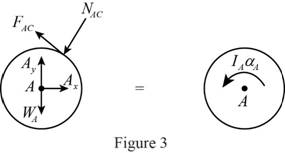
Here,
Refer to Figure 3.
Consider that the contact point between cylinder B and C is Q.
Calculate the components of forces acting along the line CQ:
Calculate the normal force at the contact point between cylinder B and C
Substitute
Calculate the angular acceleration of the cylinder A
Calculate the moment about point A by applying the equation of equilibrium:
Substitute
Calculate the angular acceleration of the cylinder A
Substitute
Hence, the angular acceleration of each cylinder
(b)
Find the final angular velocity of each disk
(b)
Answer to Problem 16.45P
The final angular velocity of each disk
Explanation of Solution
The weight of the cylinder A
The weight of the cylinder B
The weight of the cylinder C
The initial angular velocity of the cylinder A
The coefficient of the kinetic friction
The radius of the cylinder A
The radius of the cylinder B
The radius of the cylinder C
Calculation:
Refer to part (a).
The convert the unit of the initial angular velocity of the disk A
Calculate the angular velocity of cylinder A
Substitute
Calculate the tangential velocity of cylinder A
Substitute
Calculate the angular velocity of cylinder C
Substitute
Calculate the tangential velocity of cylinder C
Substitute
Calculate the time taken when tangential velocities are equal:
Substitute
Calculate the final angular velocity of the disk A
Substitute
Calculate the final angular velocity of the disk C
Substitute
Calculate the final angular velocity of the disk B
Substitute
Hence, the final angular velocity of each disk
Want to see more full solutions like this?
Chapter 16 Solutions
Vector Mechanics for Engineers: Statics and Dynamics


- Disk A has a mass mA = 4 kg, a radius rA = 300 mm, and an initial angular velocity ω0 = 300 rpm clockwise. Disk B has a mass mB = 1.6 kg, a radius rB = 180 mm, and is at rest when it is brought into contact with disk A. Knowing that µk = 0.35 between the disks and neglecting bearing friction, determine (a) the angular acceleration of each disk, (b) the reaction at the support C.arrow_forwardTwo identical giant flywheels are on 2 identical slopes at an angle alpha = 20 deg. One flywheel is rolling on its inside shaft of diameter d1 = 3 ft, and the second flywheel is rolling without slipping on its outside diameter d2 = 5 ft. They are both released from rest. The weight of the flywheel is W = 8 lbs Knowing that flywheel 1 attains a speed of v = 7.0 ft/s in t = [t] s, (if t doesn't show take any t between 5 and 10 sec) find the radius of gyration of the flywheels, following those steps: b. Find omega final c. Find the angular impulse at the point of contact between the shaft and the slope. d. Write the formula to find the final momentum. e. Solve for k, using the principle of angular impulse and momentumarrow_forwardA small 2-kg sphere B is attached to the bar AB of negligible mass that is supported at A by a pin and bracket and connected at C to a moving support D by means of a spring of constant k = 3.6 kN/m. Knowing that support D undergoes a vertical displacement δ= δm sin wf t where δm = 3 mm and ωf = 15 rad/s, determine (a ) the magnitude of the maximum angular velocity of bar AB (b) the magnitude of the maximum acceleration of sphere B.arrow_forward
- The mechanism shown is one of two identical mechanisms attached to the two sides of a 200-lb uniform rectangular door. Edge ABC of the door is guided by wheels of negligible mass that roll in horizontal and vertical tracks. A spring with a constant of k = 40 lb/ft is attached to wheel B. Knowing that the door is released from rest in the position 0= 30° with the spring unstretched, determine the velocity of wheel A just as the door reaches the vertical position.arrow_forwardIn the gear arrangement shown, gears A and C are attached to rod ABC, that is free to rotate about B, while the inner gear B is fixed. Knowing that the system is at rest, determine the magnitude of the couple M that must be applied to rod ABC, if 2.5 s later the angular velocity of the rod is to be 240 rpm clockwise. Gears A and C ABC weighs 4 lb.arrow_forwardA 1200-kg satellite designed to study the sun has an angular velocity of w0 = (0.050 rad/s)i + (0.075 rad/s)k when two small jets are activated at A and B in a direction parallel to the y axis. Knowing that the coordinate axes are principal centroidal axes, that the radii of gyration of the satellite are and that each jet produces a 50-N thrust, determine (a ) the required operating time of each jet if the angular velocity of the satellite is to be reduced to zero, (b ) the resulting change in the velocity of the mass center G.arrow_forward
- A long ladder of length l, mass m, and centroidal mass moment of inertia I is placed against a house at an angle 0=0O. Knowing that the ladder is released from rest, determine the angular velocity of the ladder when 0=02. Assume the ladder can slide freely on the horizontal ground and on the vertical wall.arrow_forwardA slender 9-lb rod can rotate in a vertical plane about a pivot at B. A spring of constant k = 30 lb/ft and of unstretched length 6 in. is attached to the rod as shown. Knowing that the rod is released from rest in the position shown, determine its angular velocity after it has rotated through 90°.arrow_forwardTwo friction wheels A and B are both rotating freely at 300 rpm counterclockwise when they are brought into contact. After 12 s of slippage, during which time each wheel has a constant angular acceleration, wheel B reaches a final angular velocity of 75 rpm counterclockwise. Determine (a) the angular acceleration of each wheel during the period of slippage, (b) the time at which the angular velocity of wheel A is equal to zero.arrow_forward
- The 80-mm-radius gear shown has a mass of 5 kg and a centroidal radius of gyration of 60 mm. The 4-kg rod AB is attached to the center of the gear and to a pin at B that slides freely in a vertical slot. Knowing that the system is released from rest when 0 = 60°, determine the velocity of the center of the gear when 0 = 20°.arrow_forwardDisk A has mass mA = 4.5 kg, radius rA = 278 mm, and initial angular velocity ω0A = 300 rpm clockwise. Disk B has mass mB = 1.0 kg, radius rB = 199 mm, and is at rest when it comes into contact with disk A. Knowing that μk = 0.45 between the disks and neglecting rolling friction ,arrow_forwardTwo identical giant flywheels are on 2 identical slopes at an angle alpha = 20 deg. One flywheel is rolling on its inside shaft of diameter d1 = 3 ft, and the second flywheel is rolling without slipping on its outside diameter d2 = 5 ft. They are both released from rest. The weight of the flywheel is W = 8 lbs 1. Knowing that flywheel 1 attains a speed of v = 7.0 ft/s in t = [t] s, (if t doesn't show take any t between 5 and 10 sec) find the radius of gyration of the flywheels, following those steps: 3. What will be the distance between the 2 flywheels? Which one is in front? a. Explain your strategy to find the distance made by each wheel. b. Find the 3 distances made by each wheel. c. Find the distance between the 2 flywheels. d. Why one is in front? 4. Using flywheel 2, what is the coefficient of static friction between the outside diameter and the ground required to prevent slipping? a. Using the 3 previous diagrams, which impulse will you consider finding the force of…arrow_forward
 Elements Of ElectromagneticsMechanical EngineeringISBN:9780190698614Author:Sadiku, Matthew N. O.Publisher:Oxford University Press
 Mechanics of Materials (10th Edition)Mechanical EngineeringISBN:9780134319650Author:Russell C. HibbelerPublisher:PEARSON
 Thermodynamics: An Engineering ApproachMechanical EngineeringISBN:9781259822674Author:Yunus A. Cengel Dr., Michael A. BolesPublisher:McGraw-Hill Education
 Control Systems EngineeringMechanical EngineeringISBN:9781118170519Author:Norman S. NisePublisher:WILEY
 Mechanics of Materials (MindTap Course List)Mechanical EngineeringISBN:9781337093347Author:Barry J. Goodno, James M. GerePublisher:Cengage Learning
 Engineering Mechanics: StaticsMechanical EngineeringISBN:9781118807330Author:James L. Meriam, L. G. Kraige, J. N. BoltonPublisher:WILEY