
Concept explainers
Videos
(a)
Find the angular acceleration of the ladder.
(a)
Answer to Problem 16.119P
The angular acceleration of the ladder is
Explanation of Solution
Given information:
The weight of the ladder is
The length of the ladder is
The coefficient of kinetic friction is
The angle is
Calculation:
Consider the acceleration due to gravity
Calculate the mass of the ladder
Substitute
Calculate the moment of inertia
Substitute
Sketch the geometry of the ladder rests on the wall as shown in Figure 1.
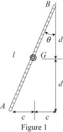
Refer to Figure 1.
Calculate the distance
Substitute
Calculate the distance
Substitute
Sketch the Free Body Diagram of the ladder as shown in Figure 2.
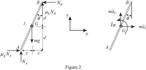
Refer to Figure 2.
Apply the Equations of Equilibrium as shown below.
Apply the Equilibrium of force along x direction as shown below.
Apply the Equilibrium of force along y direction as shown below.
Apply the Equilibrium of moment about G as shown below.
Apply the kinematics as shown below.
Calculate the acceleration
Substitute
Calculate the acceleration
Substitute
Resolving the components of i and j in Equation (5) as shown below.
Calculate the acceleration
Substitute
Hence,
Calculate the reaction
Substitute
Calculate the reaction
Substitute
Calculate the reaction
Substitute
Calculate the angular acceleration
Substitute
Substitute
Hence, the angular acceleration of the ladder is
(b)
Find the forces at A and B
(b)
Answer to Problem 16.119P
The force at A is
The force at B is
Explanation of Solution
Given information:
The weight of the ladder is
The length of the ladder is
The coefficient of kinetic friction is
The angle is
Calculation:
Refer to part (a).
The angular acceleration of the ladder is
Calculate the reaction
Substitute
Calculate the force at A
Substitute
Hence, the force at A is
Calculate the reaction
Substitute
Calculate the force at B
Substitute
Therefore, the force at B is
Want to see more full solutions like this?
Chapter 16 Solutions
Vector Mechanics for Engineers: Statics and Dynamics


- The mechanism shown is one of two identical mechanisms attached to the two sides of a 200-lb uniform rectangular door. Edge ABC of the door is guided by wheels of negligible mass that roll in horizontal and vertical tracks. A spring with a constant k is attached to wheel B in such a way that its tension is zero when 0 = 30°, Knowing that the door is released from rest in the position 0 = 45° and reaches the vertical position with an angular velocity of 0.6 rad/s, determine the spring constant k.arrow_forwardThe 10-in.-radius brake drum is attached to a larger flywheel which is not shown. The total mass moment of inertia of the flywheel and drum is 22 lb ⋅ ft ⋅ s 2 and the coefficient of kinetic friction between the drum and the brake shoe is 0.41. Knowing that the initial angular velocity is 255 rpm clockwise, determine the force which must be exerted by the hydraulic cylinder at point B if the system is to stop in 85 revolutions. DO NOT ROUND OFF IN THE SOLUTION. ROUND OFF ONLY THE FINAL ANSWERarrow_forwardThe 8-in. radius brake drum is attached to a larger flywheel that is not shown. The total mass moment of inertia of the drum and the flywheel is 15 lb.ft.s2 and the coefficient of kinetic friction between the drum and the brake shoe is 0.40. Knowing that the angular velocity of the flywheel is 450 rpm clockwise when a force P of magnitude 65 lbf. is applied to the pedal C, determine the number of the revolutions executed by the flywheel before it comes to rest. (The final answer should be in two decimal places with correct units)arrow_forward
- A uniform 144-lb cube is attached to a uniform 136-lb circular shaft as shown, and a couple M with a constant magnitude is applied to the shaft when the system is at rest. Knowing that r = 4 in., L= 12 in., and the angular velocity of the system is 960 rpm after 4 s, determine the magnitude of the couple M.arrow_forwardA wheel of radius r and centroidal radius of gyration k is released from rest on the incline shown at time t = 0. Assuming that the wheel rolls without sliding, determine (a) the velocity of its center at time t, (b) the coefficient of static friction required to prevent slipping.arrow_forwardA 3-kg bar AB is attached by a pin at D to a 4-kg square plate, which can rotate freely about a vertical axis. Knowing that the angular velocity of the plate is 120 rpm when the bar is vertical, determine (a ) the angular velocity of the plate after the bar has swung into a horizontal position and has come to rest against pin C, (b) the energy lost during the plastic impact at C.arrow_forward
- A 48-kg advertising panel of length 2a = 2.4 m and width 2b = 1.6 m is kept rotating at a constant rate w1 about its horizontal axis by a small electric motor attached at A to frame ACB. This frame itself is kept rotating at a constant rate w2 about a vertical axis by a second motor attached at C to the column CD. Knowing that the panel and the frame complete a full revolution in 6 s and 12 s, respectively, express, as a function of the angle 0, the dynamic reaction exerted on column CD by its support at D.arrow_forwardThe double pulley shown has a mass of 15 kg and a centroidal radius of gyration of 160 mm. Cylinder A and block B are attached to cords that are wrapped on the pulleys as shown. The coefficient of kinetic friction between block and the surface is 0.2. Knowing that the system is at rest in the position shown when a constant force P = 200 N is applied to cylinder A , determine (a ) the velocity of cylinder A as it strikes the ground, (b ) the total distance that block B moves before coming to rest.arrow_forwardThe shutter shown was formed by removing one quarter of a disk of 0.75-in. radius and is used to interrupt a beam of light emanating from a lens at C. Knowing that the shutter weighs 0.125 lb and rotates at the constant rate of 24 cycles per second, determine the magnitude of the force exerted by the shutter on the shaft at Aarrow_forward
- The rotor of an electric motor has an angular velocity of 3600 rpm when the load and power are cut off. The 110-lb rotor, which has a centroidal radius of gyration of 9 in., then coasts to rest. Knowing that the kinetic friction of the rotor produces a couple with a magnitude of 2.5 1b.ft determine the number of revolutions that the rotor executes before coming to rest.arrow_forwardThe 12-lb uniform disk shown has a radius of r = 3.2 in. and rotates counterclockwise. Its center C is constrained to move in a slot cut in the vertical member AB, and an 11-lb horizontal force P is applied at B to maintain contact at D between the disk and the vertical wall. The disk moves downward under the influence of gravity and the friction at D. Knowing that the coefficient of kinetic friction between the disk and the wall is 0.12 and neglecting friction in the vertical slot, determine (a) the angular acceleration of the disk, (b) the acceleration of the center C of the disk.arrow_forwardThe mechanism shown is one of two identical mechanisms attached to the two sides of a 200-lb uniform rectangular door. Edge ABC of the door is guided by wheels of negligible mass that roll in horizontal and vertical tracks. A spring with a constant of k = 40 lb/ft is attached to wheel B. Knowing that the door is released from rest in the position 0= 30° with the spring unstretched, determine the velocity of wheel A just as the door reaches the vertical position.arrow_forward
 Elements Of ElectromagneticsMechanical EngineeringISBN:9780190698614Author:Sadiku, Matthew N. O.Publisher:Oxford University Press
 Mechanics of Materials (10th Edition)Mechanical EngineeringISBN:9780134319650Author:Russell C. HibbelerPublisher:PEARSON
 Thermodynamics: An Engineering ApproachMechanical EngineeringISBN:9781259822674Author:Yunus A. Cengel Dr., Michael A. BolesPublisher:McGraw-Hill Education
 Control Systems EngineeringMechanical EngineeringISBN:9781118170519Author:Norman S. NisePublisher:WILEY
 Mechanics of Materials (MindTap Course List)Mechanical EngineeringISBN:9781337093347Author:Barry J. Goodno, James M. GerePublisher:Cengage Learning
 Engineering Mechanics: StaticsMechanical EngineeringISBN:9781118807330Author:James L. Meriam, L. G. Kraige, J. N. BoltonPublisher:WILEY