
Videos
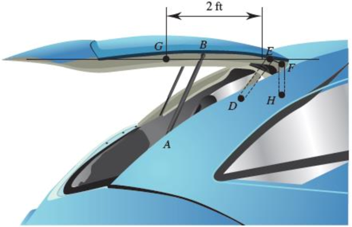
The hatchback of a car is positioned as shown to help determine the appropriate size for a damping
(a)
(b)
Fig. P16.134
(a)
The initial angular acceleration of the door.
Answer to Problem 16.134P
The initial angular acceleration of the door is
Explanation of Solution
Given information:
The weight of the door is
The mass moment of inertia of the center of gravity is
Calculation:
Consider the acceleration due to gravity as
Calculate the mass
Substitute
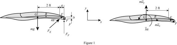
Sketch the Free Body Diagram of the door as shown in Figure 1.
Refer to Figure 1.
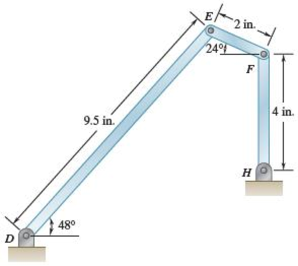
Calculate the distance
Calculate the distance
Calculate the position vectors as shown below.
The position of F with respect to H.
The position of E with respect to F.
Substitute
The position of E with respect to D.
The position of G with respect to E.
Apply the Equations of Equilibrium as shown below.
Apply the Equilibrium of forces along x direction as shown below.
Substitute
Apply the Equilibrium of forces along y direction as shown below.
Substitute
Substitute
Apply the Equilibrium of moment about G as shown below.
Calculate the acceleration at F
Substitute
Calculate the acceleration at E
Substitute
Calculate the acceleration at E
Substitute
Equating Equations (4) and (5) as shown below.
Resolving i and j components as shown below.
For i component.
For j component.
Calculate the relative acceleration
Substitute
Resolving i and j components as shown below.
For i component.
For j component.
Calculate the force at F
Substitute
Substitute
Calculate the force at E
Substitute
Substitute
Calculate the angular acceleration
Substitute
Therefore, the initial angular acceleration of the door is
(b)
The force on link FH.
Answer to Problem 16.134P
The force on link FH is
Explanation of Solution
Given information:
The weight of the door is
The mass moment of inertia of the center of gravity is
Calculation:
Refer to part (a).
The initial angular acceleration of the door is
Calculate the force at F
Substitute
Therefore, the force on link FH is
Want to see more full solutions like this?
Chapter 16 Solutions
Vector Mechanics for Engineers: Statics and Dynamics
Additional Engineering Textbook Solutions
Automotive Technology: Principles, Diagnosis, and Service (5th Edition)
Automotive Technology: Principles, Diagnosis, And Service (6th Edition) (halderman Automotive Series)
Introduction To Finite Element Analysis And Design
Fundamentals of Aerodynamics
Heat and Mass Transfer: Fundamentals and Applications
Engineering Mechanics: Dynamics (14th Edition)


- The connecting rod of a horizontal reciprocating engine is 400 mm and length of the stroke is 200mm. The mass of the reciprocating parts is 125 kg and that the connecting rod is 100 kg. The radius of gyration of the connecting rod about an axis through the centre of gravity is 120 mm and the distance of centre of gravity of the connecting rod from big end centre is 160 mm. The engine runs at750 r.p.m. Determine graphically the torque exerted on the crankshaft when the crank has turned 30° from the inner dead centre.arrow_forwardA shaft turning at a uniform speed carries two uniform discs A and B of masses 10kg and 8kg respectively. The centres of the mass of the discs are each 2.5mm from the axis of rotation. The radii to the centres of mass are at right angles. The shaft is carried in bearings C and D between A and B such that AC = 0.3m, AD = 0.9m and AB = 1.2m. It is required to make dynamic loading on the bearings equal and a minimum for any given shaft speed by adding a mass at a radius 25mm in a plane E. Determine: (a) The magnitude of the mass in plane E and its angular position relative to the mass in plane A (b) The distance of the plane E from plane A (c) The dynamic loading on each bearing when the mass in plane E has been attached and the shaft rotates at 200 rev/min. For the bearing loads in the opposite direction determine all the unknown values. For the bearing loads in the same direction, show the diagrams and equations only to use for a possible solution.arrow_forwardA shaft turning at a uniform speed carries two uniform discs A and B of masses 10kg and 8kg respectively. The centres of the mass of the discs are each 2.5mm from the axis of rotation. The radii to the centres of mass are at right angles. The shaft is carried in bearings C and D between A and B such that AC = 0.3m, AD = 0.9m and AB = 1.2m. It is required to make dynamic loading on the bearings equal and a minimum for any given shaft speed by adding a mass at a radius 25mm in a plane E. USING THE METHOD OF DRAWING m*r and m*r*l diagram Determine: The magnitude of the mass in plane E and its angular position relative to the mass in plane A The distance of the plane E from plane A The dynamic loading on each bearing when the mass in plane E has been attached and the shaft rotates at 200 rev/min. For the bearing loads in the opposite direction determine all the unknown values. For the bearing loads in the same direction, show the diagrams and equations only to use for a possible…arrow_forward
- A shaft turning at a uniform speed carries two uniform discs A and B of masses 10kg and 8kg respectively. The centres of the mass of the discs are each 2.5mm from the axis of rotation. The radii to the centres of mass are at right angles. The shaft is carried in bearings C and D between A and B such that AC = 0.3m, AD = 0.9m and AB = 1.2m. It is required to make dynamic loading on the bearings equal and a minimum for any given shaft speed by adding a mass at a radius 25mm in a plane E. Determine: The magnitude of the mass in plane E and its angular position relative to the mass in plane A The distance of the plane E from plane A PS – Use graphical methods to solve the balancing problemarrow_forwardA shaft turning at a uniform speed carries two uniform discs A and B of masses 10kg and 8kg respectively. The centres of the mass of the discs are each 2.5mm from the axis of rotation. The radii to the centres of mass are at right angles. The shaft is carried in bearings C and D between A and B such that AC = 0.3m, AD = 0.9m and AB = 1.2m. It is required to make dynamic loading on the bearings equal and a minimum for any given shaft speed by adding a mass at a radius 25mm in a plane E. Determine: The dynamic loading on each bearing when the mass in plane E has been attached and the shaft rotates at 200 rev/min. For the bearing loads in the opposite direction determine all the unknown values. For the bearing loads in the same direction, show the diagrams and equations only to use for a possible solution. PS – Use graphical methods to solve the balancing problemarrow_forwardA load of mass 230 kg is lifted by means of a rope which is wound several times round a drum and which then supports a balance mass of 140 kg. As the load rises, the balance mass falls. The drum has a diameter of 1.2 m and a radius of gyration of 530 mm and its mass is 70 kg. The frictional resistance to the movement of the load is 110 N. and that to the movement of the balance mass 90 N. The frictional torque on the drum shaft is 80 N-m. 2. Find the torque required on the drum, and also the power required, at the instant when the load has an upward velocity of 2.5 m/s and an upward acceleration of 1.2 m/s?. [Ans. 916.2 N-m ; 4.32 kW]arrow_forward
- A uniform rod of mass M = 2.3 kg and length L = 0.2 m, lying on a frictionless horizontal plane, is free to pivot about a vertical axis through one end, as shown. The moment of inertia of the rod about this axis is given by 1/3 ML2. If a force F = 7 N, q = 47° acts as shown, what is the resulting angular acceleration (in rad/s2) about the pivot point?arrow_forward3.32). As shown in Figure 3, a yo-yo toy is formed by wrapping a massless cord around adisk of radius R= 0.2 m and mass M=3 kg. The cord is vertical and its top end is fixed and the disk isinitially stationary. The cord remains vertical for the entire motion and does not slide on the disk.When the disk is released from rest, it falls down by a distance H=0.8 m, The moment of inertia ofthe disk around its center is I disk=1/2mdiskR^2a . Find the angular acceleration of the disk when it is lowered by a distance H.b . Find the angular velocity of the disk when it is lowered by a distance H.arrow_forwardA shaft carries four masses A, B, C and D of magnitude 10 kg, 20 kg, 15 kg and 25 kg respectively and revolving at radii 100 mm, 50 mm, 80 mm and 120mm in planes measured from A at 100 mm, 300 mm and 500 mm. The angles between the cranks measured anticlockwise are A to B = 40°, B to C = 50° and C to D = 150°. The balancing masses are to be placed in planes X and Y. The distance between the planes A and X is 50 mm, between X and Y is 350 mm. If the balancing masses revolve at a radius of 50 mm, find the magnitude for mass on plane X (consider plane X as the refernce plane).arrow_forward
- A crate of mass 451 kg is being lifted by the mechanism shown in the figure. The two cables are wrapped around their respective pulleys, which have radii of 0.600 and 0.200 m. The pulleys are fastened together to form a dual pulley and turn as a single unit about the center axle, relative to which the combined moment of inertia is 51.0 kg · m2. The cables roll on the dual pulley without slipping. A tension of magnitude 2150 N is maintained in the cable attached to the motor. Find (a) the angular acceleration of the dual pulley and (b) the tension in the cable connected to the crate.arrow_forwardA 7.5-kg disk A radius 0.6 m initially rotating clockwise at 300 rev/min is engaged with an 8.5-kg disk B radius 0.4 m initially rotating counter-clockwise at 700 rev/min, where the moment of inertia of a disk is given as I=1/2mr^2. Determine their combined angular speed (in rpm) and direction of rotation after the meshing of the two disk.arrow_forwardA uniform disk of mass m = 4 kg and radius r = 150 mm is supported by a belt ABCD that is bolted to the disk at B and C. If the belt suddenly breaks at a point located between A and B, draw the FBD and KD for the disk immediately after the break.arrow_forward
 Elements Of ElectromagneticsMechanical EngineeringISBN:9780190698614Author:Sadiku, Matthew N. O.Publisher:Oxford University Press
 Mechanics of Materials (10th Edition)Mechanical EngineeringISBN:9780134319650Author:Russell C. HibbelerPublisher:PEARSON
 Thermodynamics: An Engineering ApproachMechanical EngineeringISBN:9781259822674Author:Yunus A. Cengel Dr., Michael A. BolesPublisher:McGraw-Hill Education
 Control Systems EngineeringMechanical EngineeringISBN:9781118170519Author:Norman S. NisePublisher:WILEY
 Mechanics of Materials (MindTap Course List)Mechanical EngineeringISBN:9781337093347Author:Barry J. Goodno, James M. GerePublisher:Cengage Learning
 Engineering Mechanics: StaticsMechanical EngineeringISBN:9781118807330Author:James L. Meriam, L. G. Kraige, J. N. BoltonPublisher:WILEY