
Concept explainers
Videos
Two rotating rods in the vertical plane are connected by a slider block P of negligible mass. The rod attached at A has a mass of 0.8 kg and a length of 160 mm. Rod BP has a mass of 1 kg and is 200 mm long and the friction between block P and AE is negligible. The motion of the system is controlled by a couple M applied to bar BP. Knowing that at the instant shown rod BP has an angular velocity of 20 rad/s clockwise and an angular acceleration of 80 rad/s2 clockwise, determine (a) the couple M, (b) the components of the force exerted on AE by block P.
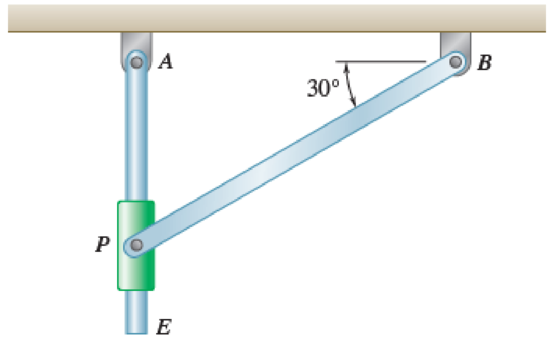
Fig. P16.141 and Fig. P16.142
(a)
Find the value of couple M.
Answer to Problem 16.142P
The value of couple M is
Explanation of Solution
Given information:
The mass of the rod AE is
The mass of the rod BP is
The length of the rod AE is
The length of the rod BP is
The angular velocity is
The angular acceleration is
Calculation:
Consider the acceleration due to gravity as
Calculate the position vector
The position of P with respect to A.
The position of P with respect to B.
The position of P with respect to E.
The angular velocity of rod BP in vector form is
The angular acceleration of rod BP in vector form is
Calculate the velocity of rod BP
Substitute
Consider the relative angular velocity of rod AE as
Calculate the velocity of point P
Substitute
Resolving i and j components as shown below.
Calculate the acceleration of rod BP
Substitute
Calculate the acceleration of point P with respect to point E
Substitute
Calculate the acceleration of point P
Substitute
Resolving i and j components as shown below.
Calculate the weight of
For rod AE.
Substitute
For rod BP.
Substitute
Calculate the mass moment of inertia
For rod AE.
Substitute
For rod BP.
Substitute
Calculate the position vector
The position of mass center G with respect to the rod AE.
The position of mass center H with respect to the rod BP.
Calculate the acceleration of point G
Substitute
Calculate the acceleration of point H
Substitute
Calculate the inertial terms of the mass center
For rod AE.
For rod BP.
Calculate the effective couples at mass center
For rod AE.
For rod BP.
Sketch the Free Body Diagram of rod AE as shown in Figure 1.
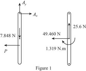
Refer to Figure 1.
Apply the Equilibrium of moment about A as shown below.
Sketch the Free Body Diagram of rod BP as shown in Figure 2.
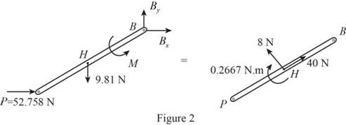
Refer to Figure 2.
Apply the Equilibrium of moment about A as shown below.
Hence, the couple M is
(b)
Find the components of the force exerted on AE by block.
Answer to Problem 16.142P
The components of the force exerted on AE by block is
Explanation of Solution
Given information:
The mass of the rod AE is
The mass of the rod BP is
The length of the rod AE is
The length of the rod BP is
The angular velocity is
The angular acceleration is
Calculation:
Refer to part (a).
The components of the force exerted on AE by block
Therefore, the components of the force exerted on AE by block is
Want to see more full solutions like this?
Chapter 16 Solutions
Vector Mechanics for Engineers: Statics and Dynamics
Additional Engineering Textbook Solutions
Introduction to Heat Transfer
INTERNATIONAL EDITION---Engineering Mechanics: Statics, 14th edition (SI unit)
Thermodynamics: An Engineering Approach
Mechanics of Materials (10th Edition)
Thermodynamics: An Engineering Approach
Vector Mechanics for Engineers: Statics, 11th Edition


- The shutter shown was formed by removing one quarter of a disk of 0.75-in. radius and is used to interrupt a beam of light emanating from a lens at C. Knowing that the shutter weighs 0.125 lb and rotates at the constant rate of 24 cycles per second, determine the magnitude of the force exerted by the shutter on the shaft at Aarrow_forwardThe rotor of an electric motor has an angular velocity of 3570 rpm when the load and power are cut off. The 65-kg rotor, which has a centroidal radius of gyration of 175mm, until it reaches the maximum speed of 5250 rpm. Knowing that the kinetic friction results in a couple of magnitude 4.5 N.m exerted on the rotor, determine the number of revolutions that the rotor executes, before achieving its maximum speed and the time it took. (The final answer should be in two decimal places with correct units)arrow_forwardThe 10-in.-radius brake drum is attached to a larger flywheel which is not shown. The total mass moment of inertia of the flywheel and drum is 22 lb ⋅ ft ⋅ s 2 and the coefficient of kinetic friction between the drum and the brake shoe is 0.41. Knowing that the initial angular velocity is 255 rpm clockwise, determine the force which must be exerted by the hydraulic cylinder at point B if the system is to stop in 85 revolutions. DO NOT ROUND OFF IN THE SOLUTION. ROUND OFF ONLY THE FINAL ANSWERarrow_forward
- Disk A, of weight 5 lb and radius r = 3 in., is at rest when it is placed in contact with a belt that moves at a constant speed v = 50 ft/s. Knowing that μk = 0.20 between the disk and the belt, determine the time required for the disk to reach a constant angular velocity.arrow_forwardA cylinder of radius r and weight W with an initial counterclockwise angular velocity w0 is placed in the corner formed by the floor and a vertical wall. Denoting by μk the coefficient of kinetic friction between the cylinder and the wall and the floor, derive an expression for the time required for the cylinder to come to rest.arrow_forwardThe 10-in.-radius brake drum is attached to a larger flywheel which is not shown. The total mass moment of inertia of the flywheel and drum is 22 lb ⋅ ft ⋅ s 2 and the coefficient of kinetic friction between the drum and the brake shoe is 0.41. Knowing that the initial angular velocity is 255 rpm clockwise, determine the force which must be exerted by the hydraulic cylinder at point B if the system is to stop in 85 revolutions.arrow_forward
- The 12-lb uniform disk shown has a radius of r = 3.2 in. and rotates counterclockwise. Its center C is constrained to move in a slot cut in the vertical member AB, and an 11-lb horizontal force P is applied at B to maintain contact at D between the disk and the vertical wall. The disk moves downward under the influence of gravity and the friction at D. Knowing that the coefficient of kinetic friction between the disk and the wall is 0.12 and neglecting friction in the vertical slot, determine (a) the angular acceleration of the disk, (b) the acceleration of the center C of the disk.arrow_forwardTwo identical 4-lb slender rods AB and BC are connected by a pin at B and by the cord AC. The assembly rotates in a vertical plane under the combined effect of gravity and a 6-lb·ft couple M applied to rod AB. Knowing that in the position shown the angular velocity of the assembly is zero, determine (a) the angular acceleration of the assembly, (b) the tension in cord AC.arrow_forwardA bar of mass m = 5 kg is held as shown between four disks each of mass m’ = 2 kg and radius r = 75 mm. Knowing that the forces exerted on the disks are sufficient to prevent slipping and that the bar is released from rest, for each of the cases shown, determine the velocity of the bar after it has moved through the distance h.arrow_forward
- The 10-in.-radius brake drum is attached to a larger flywheel which is not shown. The total mass moment of inertia of the flywheel and drum is 22 lb ⋅ ft ⋅ s 2 and the coefficient of kinetic friction between the drum and the brake shoe is 0.41. Knowing that the initial angular velocity is 255 rpm clockwise, determine the force which must be exerted by the hydraulic cylinder at point B if the system is to stop in 85 revolutions. determine the force which must be exerted by the hydraulic cylinder at point B if the system is to stop in 85 revolutions. DO NOT ROUND OFF IN THE SOLUTION. ROUND OFF ONLY IN 2 DECIMAL PLACE IN THE FINAL ANSWER.arrow_forwardTwo identical giant flywheels are on 2 identical slopes at an angle alpha = 20 deg. One flywheel is rolling on its inside shaft of diameter d1 = 3 ft, and the second flywheel is rolling without slipping on its outside diameter d2 = 5 ft. They are both released from rest. The weight of the flywheel is W = 8 lbs Knowing that flywheel 1 attains a speed of v = 7.0 ft/s in t = [t] s, (if t doesn't show take any t between 5 and 10 sec) find the radius of gyration of the flywheels, following those steps: b. Find omega final c. Find the angular impulse at the point of contact between the shaft and the slope. d. Write the formula to find the final momentum. e. Solve for k, using the principle of angular impulse and momentumarrow_forward
 Elements Of ElectromagneticsMechanical EngineeringISBN:9780190698614Author:Sadiku, Matthew N. O.Publisher:Oxford University Press
 Mechanics of Materials (10th Edition)Mechanical EngineeringISBN:9780134319650Author:Russell C. HibbelerPublisher:PEARSON
 Thermodynamics: An Engineering ApproachMechanical EngineeringISBN:9781259822674Author:Yunus A. Cengel Dr., Michael A. BolesPublisher:McGraw-Hill Education
 Control Systems EngineeringMechanical EngineeringISBN:9781118170519Author:Norman S. NisePublisher:WILEY
 Mechanics of Materials (MindTap Course List)Mechanical EngineeringISBN:9781337093347Author:Barry J. Goodno, James M. GerePublisher:Cengage Learning
 Engineering Mechanics: StaticsMechanical EngineeringISBN:9781118807330Author:James L. Meriam, L. G. Kraige, J. N. BoltonPublisher:WILEY