
Vector Mechanics for Engineers: Statics and Dynamics
12th Edition
ISBN: 9781259638091
Author: Ferdinand P. Beer, E. Russell Johnston Jr., David Mazurek, Phillip J. Cornwell, Brian Self
Publisher: McGraw-Hill Education
expand_more
expand_more
format_list_bulleted
Concept explainers
Videos
Textbook Question
Chapter 16.2, Problem 16.4CQ
A cord is attached to a spool when a force P is applied to the cord as shown. Assuming the spool rolls without slipping, what direction does the spool move for each case?
Case 1: a. left b. right c. It would not move.
Case 2: a. left b. right c. It would not move.
Case 3: a. left b. right c. It would not move.
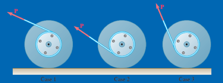
Fig. P16.CQ4 and P16.CQ5
Expert Solution & Answer
Want to see the full answer?
Check out a sample textbook solution
Students have asked these similar questions
The mechanism shown is one of two identical mechanisms attached to the two sides of a 200-lb uniform rectangular door. Edge ABC of the door is guided by wheels of negligible mass that roll in horizontal and vertical tracks. A spring with a constant k is attached to wheel B in such a way that its tension is zero when 0 = 30°, Knowing that the door is released from rest in the position 0 = 45° and reaches the vertical position with an angular velocity of 0.6 rad/s, determine the spring constant k.
A uniform 144-lb cube is attached to a uniform 136-lb circular shaft as shown, and a couple M with a constant magnitude is applied to the shaft when the system is at rest. Knowing that r = 4 in., L= 12 in., and the angular velocity of the system is 960 rpm after 4 s, determine the magnitude of the couple M.
The 8-in. radius brake drum is attached to a larger flywheel that is not
shown. The total mass moment of inertia of the drum and the flywheel is
15 lb.ft.s2 and the coefficient of kinetic friction between the drum and
the brake shoe is 0.40. Knowing that the angular velocity of the flywheel
is 450 rpm clockwise when a force P of magnitude 65 lbf. is applied to
the pedal C, determine the number of the revolutions executed by the
flywheel before it comes to rest.
(The final answer should be in two decimal places with correct units)
Chapter 16 Solutions
Vector Mechanics for Engineers: Statics and Dynamics
Ch. 16.1 - Two pendulums, A and B, with the masses and...Ch. 16.1 - Two pendulums, A and B, with the masses and...Ch. 16.1 - Two solid cylinders, A and B, have the same mass m...Ch. 16.1 - Prob. 16.1FBPCh. 16.1 - Prob. 16.2FBPCh. 16.1 - Prob. 16.3FBPCh. 16.1 - The 400-lb crate shown is lowered by means of two...Ch. 16.1 - A 60-lb uniform thin panel is placed in a truck...Ch. 16.1 - A 60-lb uniform thin panel is placed in a truck...Ch. 16.1 - A loading car is at rest on a track forming an...
Ch. 16.1 - A 2100-lb rear-wheel-drive tractor carries a 900...Ch. 16.1 - A uniform rod BC of mass 4 kg is connected to a...Ch. 16.1 - A 2000-kg truck is being used to lift a 400-kg...Ch. 16.1 - The support bracket shown is used to transport a...Ch. 16.1 - Prob. 16.8PCh. 16.1 - A 20-kg cabinet is mounted on casters that allow...Ch. 16.1 - Solve Prob. 16.9, assuming that the casters are...Ch. 16.1 - Prob. 16.11PCh. 16.1 - Prob. 16.12PCh. 16.1 - The retractable shelf shown is supported by two...Ch. 16.1 - Bars AB and BE, each with a mass of 4 kg, are...Ch. 16.1 - At the instant shown, the tensions in the vertical...Ch. 16.1 - Three bars, each of mass 3 kg, are welded together...Ch. 16.1 - Members ACE and DCB are each 600 mm long and are...Ch. 16.1 - A prototype rotating bicycle rack is designed to...Ch. 16.1 - The control rod AC is guided by two pins that...Ch. 16.1 - The coefficients of friction between the 30-lb...Ch. 16.1 - Prob. 16.21PCh. 16.1 - Prob. 16.22PCh. 16.1 - For a rigid body in translation, show that the...Ch. 16.1 - For a rigid body in centroidal rotation, show that...Ch. 16.1 - It takes 10 min for a 2.4-Mg flywheel to coast to...Ch. 16.1 - The rotor of an electric motor has an angular...Ch. 16.1 - The 10-in.-radius brake drum is attached to a...Ch. 16.1 - The 10-in.-radius brake drum is attached to a...Ch. 16.1 - The 100-mm-radius brake drum is attached to a...Ch. 16.1 - The 180-mm-radius disk is at rest when it is...Ch. 16.1 - Solve Prob. 16.30, assuming that the direction of...Ch. 16.1 - In order to determine the mass moment of inertia...Ch. 16.1 - The flywheel shown has a radius of 20 in., a...Ch. 16.1 - Each of the double pulleys shown has a mass moment...Ch. 16.1 - Two disks A and B, of mass mA = 2 kg and mB = 4...Ch. 16.1 - Two disks A and B, of mass mA = 2 kg and mB = 4...Ch. 16.1 - Gear A weighs 1 lb and has a radius of gyration of...Ch. 16.1 - The 25-lb double pulley shown is at rest and in...Ch. 16.1 - A belt of negligible mass passes between cylinders...Ch. 16.1 - Prob. 16.40PCh. 16.1 - Disk A has a mass of 6 kg and an initial angular...Ch. 16.1 - Prob. 16.42PCh. 16.1 - Disk A has a mass mA = 4 kg, a radius rA = 300 mm,...Ch. 16.1 - Disk B is at rest when it is brought into contact...Ch. 16.1 - Prob. 16.45PCh. 16.1 - Prob. 16.46PCh. 16.1 - For a rigid body in plane motion, show that the...Ch. 16.1 - A uniform slender rod AB rests on a frictionless...Ch. 16.1 - Prob. 16.49PCh. 16.1 - Prob. 16.50PCh. 16.1 - Prob. 16.51PCh. 16.1 - A 250-lb satellite has a radius of gyration of 24...Ch. 16.1 - A rectangular plate of mass 5 kg is suspended from...Ch. 16.1 - Prob. 16.54PCh. 16.1 - A drum with a 200-mm radius is attached to a disk...Ch. 16.1 - A drum with a 200-mm radius is attached to a disk...Ch. 16.1 - The 12-lb uniform disk shown has a radius of r =...Ch. 16.1 - Prob. 16.58PCh. 16.1 - Prob. 16.59PCh. 16.1 - 16.60 and 16.61The 400-lb crate shown is lowered...Ch. 16.1 - Prob. 16.61PCh. 16.1 - Two uniform cylinders, each of weight W = 14 lb...Ch. 16.1 - Prob. 16.63PCh. 16.1 - Prob. 16.64PCh. 16.1 - A uniform slender bar AB with a mass m is...Ch. 16.1 - Prob. 16.66PCh. 16.1 - 16.66 through 16.68A thin plate of the shape...Ch. 16.1 - 16.66 through 16.68A thin plate of the shape...Ch. 16.1 - A sphere of radius r and mass m is projected along...Ch. 16.1 - Solve Prob. 16.69, assuming that the sphere is...Ch. 16.1 - A bowler projects an 8-in.-diameter ball weighing...Ch. 16.1 - Prob. 16.72PCh. 16.1 - A uniform sphere of radius r and mass m is placed...Ch. 16.1 - A sphere of radius r and mass m has a linear...Ch. 16.2 - A cord is attached to a spool when a force P is...Ch. 16.2 - Prob. 16.5CQCh. 16.2 - Prob. 16.6CQCh. 16.2 - Prob. 16.7CQCh. 16.2 - Prob. 16.5FBPCh. 16.2 - Two identical 4-lb slender rods AB and BC are...Ch. 16.2 - Prob. 16.7FBPCh. 16.2 - Prob. 16.8FBPCh. 16.2 - Show that the couple I of Fig. 16.15 can be...Ch. 16.2 - A uniform slender rod of length L = 900 mm and...Ch. 16.2 - A crate of mass 80 kg is held in the position...Ch. 16.2 - A uniform slender rod of length L = 36 in. and...Ch. 16.2 - In Prob. 16.78, determine (a) the distance h for...Ch. 16.2 - An athlete performs a leg extension on a machine...Ch. 16.2 - Prob. 16.81PCh. 16.2 - A turbine disk weighing 50 lb rotates at a...Ch. 16.2 - The 80-lb tailgate of a car is supported by the...Ch. 16.2 - A uniform rod of length L and mass m is supported...Ch. 16.2 - Three stage lights are mounted on a pipe fixture...Ch. 16.2 - An adapted launcher uses a torsional spring about...Ch. 16.2 - A 4-kg slender rod is welded to the edge of a 3-kg...Ch. 16.2 - Prob. 16.88PCh. 16.2 - The object ABC consists of two slender rods welded...Ch. 16.2 - A 3.5-kg slender rod AB and a 2-kg slender rod BC...Ch. 16.2 - A 9-kg uniform disk is attached to the 5-kg...Ch. 16.2 - Derive the equation MC=IC for the rolling disk of...Ch. 16.2 - Prob. 16.93PCh. 16.2 - Prob. 16.94PCh. 16.2 - Prob. 16.95PCh. 16.2 - Prob. 16.96PCh. 16.2 - A 40-kg flywheel of radius R = 0.5 m is rigidly...Ch. 16.2 - Prob. 16.98PCh. 16.2 - 16.98 through 16.101A drum of 80-mm radius is...Ch. 16.2 - 16.98 through 16.101A drum of 80-mm radius is...Ch. 16.2 - 16.98 through 16.101A drum of 80-mm radius is...Ch. 16.2 - 16.102 through 16.105A drum of 4-in. radius is...Ch. 16.2 - 16.102 through 16.105A drum of 4-in. radius is...Ch. 16.2 - 16.102 through 16.105A drum of 4-in. radius is...Ch. 16.2 - 16.102 through 16.105A drum of 4-in. radius is...Ch. 16.2 - 16.106 and 16.107A 12-in.-radius cylinder of...Ch. 16.2 - 16.106 and 16.107A 12-in.-radius cylinder of...Ch. 16.2 - Gear C has a mass of 5 kg and a centroidal radius...Ch. 16.2 - Two uniform disks A and B, each with a mass of 2...Ch. 16.2 - A single-axis personal transport device starts...Ch. 16.2 - A hemisphere of weight W and radius r is released...Ch. 16.2 - A hemisphere of weight W and radius r is released...Ch. 16.2 - The center of gravity G of a 1.5-kg unbalanced...Ch. 16.2 - A small clamp of mass mB is attached at B to a...Ch. 16.2 - Prob. 16.115PCh. 16.2 - A 4-lb bar is attached to a 10-lb uniform cylinder...Ch. 16.2 - The uniform rod AB with a mass m and a length of...Ch. 16.2 - Prob. 16.118PCh. 16.2 - Prob. 16.119PCh. 16.2 - Prob. 16.120PCh. 16.2 - End A of the 6-kg uniform rod AB rests on the...Ch. 16.2 - End A of the 6-kg uniform rod AB rests on the...Ch. 16.2 - End A of the 8-kg uniform rod AB is attached to a...Ch. 16.2 - The 4-kg uniform rod ABD is attached to the crank...Ch. 16.2 - The 3-lb uniform rod BD is connected to crank AB...Ch. 16.2 - The 3-lb uniform rod BD is connected to crank AB...Ch. 16.2 - The test rig shown was developed to perform...Ch. 16.2 - Solve Prob. 16.127 for = 90. 16.127The test rig...Ch. 16.2 - The 4-kg uniform slender bar BD is attached to bar...Ch. 16.2 - The motion of the uniform slender rod of length L...Ch. 16.2 - At the instant shown, the 20-ft-long, uniform...Ch. 16.2 - A driver starts his car with the door on the...Ch. 16.2 - Prob. 16.133PCh. 16.2 - The hatchback of a car is positioned as shown to...Ch. 16.2 - The 6-kg rod BC connects a 10-kg disk centered at...Ch. 16.2 - Prob. 16.136PCh. 16.2 - In the engine system shown, l = 250 mm and b = 100...Ch. 16.2 - Solve Prob. 16.137 when = 90. 16.137In the engine...Ch. 16.2 - The 4-lb uniform slender rod AB, the 8-lb uniform...Ch. 16.2 - The 4-lb uniform slender rod AB, the 8-lb uniform...Ch. 16.2 - Two rotating rods in the vertical plane are...Ch. 16.2 - Two rotating rods in the vertical plane are...Ch. 16.2 - Two disks, each with a mass m and a radius r, are...Ch. 16.2 - A uniform slender bar AB of mass m is suspended as...Ch. 16.2 - A uniform rod AB, of mass 15 kg and length 1 m, is...Ch. 16.2 - The uniform slender 2-kg bar BD is attached to the...Ch. 16.2 - Prob. 16.147PCh. 16.2 - Prob. 16.148PCh. 16.2 - Prob. 16.149PCh. 16.2 - Prob. 16.150PCh. 16.2 - (a) Determine the magnitude and the location of...Ch. 16.2 - Prob. 16.152PCh. 16 - A cyclist is riding a bicycle at a speed of 20 mph...Ch. 16 - The forklift truck shown weighs 3200 lb and is...Ch. 16 - The total mass of the Baja car and driver,...Ch. 16 - Identical cylinders of mass m and radius r are...Ch. 16 - Prob. 16.157RPCh. 16 - The uniform rod AB of weight W is released from...Ch. 16 - Prob. 16.159RPCh. 16 - Prob. 16.160RPCh. 16 - A cylinder with a circular hole is rolling without...Ch. 16 - Two 3-kg uniform bars are connected to form the...Ch. 16 - A crate of mass 80 kg is held in the position...Ch. 16 - The Geneva mechanism shown is used to provide an...
Additional Engineering Textbook Solutions
Find more solutions based on key concepts
Select a mechanical component from Part 3 of this book (roller bearings, springs, etc.), go to the Internet, an...
Shigley's Mechanical Engineering Design (McGraw-Hill Series in Mechanical Engineering)
A 20-lb force is applied to the control rod AB as shown. Knowing that the length of the rod is 9 in. and that t...
Statics and Mechanics of Materials
Locate the centroid of the area. Prob. 9-17
Engineering Mechanics: Statics
For the beam loading of Figure P334, draw the complete shearing force and bending moment diagrams, and determin...
Machine Elements in Mechanical Design (6th Edition) (What's New in Trades & Technology)
What types of polymers are most commonly blow molded?
DeGarmo's Materials and Processes in Manufacturing
Determine the length of the cantilevered beam so that the maximum bending stress in the beam is equivalent to t...
Mechanics of Materials (10th Edition)
Knowledge Booster


Learn more about
Need a deep-dive on the concept behind this application? Look no further. Learn more about this topic, mechanical-engineering and related others by exploring similar questions and additional content below.Similar questions
- The shutter shown was formed by removing one quarter of a disk of 0.75-in. radius and is used to interrupt a beam of light emanating from a lens at C. Knowing that the shutter weighs 0.125 lb and rotates at the constant rate of 24 cycles per second, determine the magnitude of the force exerted by the shutter on the shaft at Aarrow_forwardThe 10-in.-radius brake drum is attached to a larger flywheel which is not shown. The total mass moment of inertia of the flywheel and drum is 22 lb ⋅ ft ⋅ s 2 and the coefficient of kinetic friction between the drum and the brake shoe is 0.41. Knowing that the initial angular velocity is 255 rpm clockwise, determine the force which must be exerted by the hydraulic cylinder at point B if the system is to stop in 85 revolutions. DO NOT ROUND OFF IN THE SOLUTION. ROUND OFF ONLY THE FINAL ANSWERarrow_forwardA 9-kg uniform disk is attached to the 5-kg slender rod AB by means of frictionless pins at B and C. The assembly rotates in a vertical plane under the combined effect of gravity and of a couple M that is applied to rod AB. Knowing that at the instant shown the assembly has an angular velocity of 6 rad/s and an angular acceleration of 25 rad/s2 , both counterclockwise, determine (a) the couple M, (b) the force exerted by pin C on member ABarrow_forward
- The 10-in.-radius brake drum is attached to a larger flywheel which is not shown. The total mass moment of inertia of the flywheel and drum is 22 lb ⋅ ft ⋅ s 2 and the coefficient of kinetic friction between the drum and the brake shoe is 0.41. Knowing that the initial angular velocity is 255 rpm clockwise, determine the force which must be exerted by the hydraulic cylinder at point B if the system is to stop in 85 revolutions.arrow_forwardThe 10-in.-radius brake drum is attached to a larger flywheel which is not shown. The total mass moment of inertia of the flywheel and drum is 22 lb ⋅ ft ⋅ s 2 and the coefficient of kinetic friction between the drum and the brake shoe is 0.41. Knowing that the initial angular velocity is 255 rpm clockwise, determine the force which must be exerted by the hydraulic cylinder at point B if the system is to stop in 85 revolutions. determine the force which must be exerted by the hydraulic cylinder at point B if the system is to stop in 85 revolutions. DO NOT ROUND OFF IN THE SOLUTION. ROUND OFF ONLY IN 2 DECIMAL PLACE IN THE FINAL ANSWER.arrow_forwardTwo identical 4-lb slender rods AB and BC are connected by a pin at B and by the cord AC. The assembly rotates in a vertical plane under the combined effect of gravity and a 6-lb·ft couple M applied to rod AB. Knowing that in the position shown the angular velocity of the assembly is zero, determine (a) the angular acceleration of the assembly, (b) the tension in cord AC.arrow_forward
- A 3-kg bar AB is attached by a pin at D to a 4-kg square plate, which can rotate freely about a vertical axis. Knowing that the angular velocity of the plate is 120 rpm when the bar is vertical, determine (a ) the angular velocity of the plate after the bar has swung into a horizontal position and has come to rest against pin C, (b) the energy lost during the plastic impact at C.arrow_forwardA 1200-kg satellite designed to study the sun has an angular velocity of w0 = (0.050 rad/s)i + (0.075 rad/s)k when two small jets are activated at A and B in a direction parallel to the y axis. Knowing that the coordinate axes are principal centroidal axes, that the radii of gyration of the satellite are and that each jet produces a 50-N thrust, determine (a ) the required operating time of each jet if the angular velocity of the satellite is to be reduced to zero, (b ) the resulting change in the velocity of the mass center G.arrow_forwardThe double pulley shown has a mass of 15 kg and a centroidal radius of gyration of 160 mm. Cylinder A and block B are attached to cords that are wrapped on the pulleys as shown. The coefficient of kinetic friction between block and the surface is 0.2. Knowing that the system is at rest in the position shown when a constant force P = 200 N is applied to cylinder A , determine (a ) the velocity of cylinder A as it strikes the ground, (b ) the total distance that block B moves before coming to rest.arrow_forward
- A wheel of radius r and centroidal radius of gyration k is released from rest on the incline shown at time t = 0. Assuming that the wheel rolls without sliding, determine (a) the velocity of its center at time t, (b) the coefficient of static friction required to prevent slipping.arrow_forwardIn the gear arrangement shown, gears A and C are attached to rod ABC, that is free to rotate about B, while the inner gear B is fixed. Knowing that the system is at rest, determine the magnitude of the couple M that must be applied to rod ABC, if 2.5 s later the angular velocity of the rod is to be 240 rpm clockwise. Gears A and C ABC weighs 4 lb.arrow_forwardTwo uniform cylinders, each of weight W = 14 lb and radius r = 5 in., are connected by a belt as shown. Knowing that at the instant shown the angular velocity of cylinder B is 30 rad/s clockwise, determine (a) the distance through which cylinder A will rise before the angular velocity of cylinder B is reduced to 5 rad/s, (b ) the tension in the portion of belt connecting the two cylinders.arrow_forward
arrow_back_ios
SEE MORE QUESTIONS
arrow_forward_ios
Recommended textbooks for you
 Elements Of ElectromagneticsMechanical EngineeringISBN:9780190698614Author:Sadiku, Matthew N. O.Publisher:Oxford University Press
 Mechanics of Materials (10th Edition)Mechanical EngineeringISBN:9780134319650Author:Russell C. HibbelerPublisher:PEARSON
 Thermodynamics: An Engineering ApproachMechanical EngineeringISBN:9781259822674Author:Yunus A. Cengel Dr., Michael A. BolesPublisher:McGraw-Hill Education
 Control Systems EngineeringMechanical EngineeringISBN:9781118170519Author:Norman S. NisePublisher:WILEY
 Mechanics of Materials (MindTap Course List)Mechanical EngineeringISBN:9781337093347Author:Barry J. Goodno, James M. GerePublisher:Cengage Learning
 Engineering Mechanics: StaticsMechanical EngineeringISBN:9781118807330Author:James L. Meriam, L. G. Kraige, J. N. BoltonPublisher:WILEY
Elements Of Electromagnetics
Mechanical Engineering
ISBN:9780190698614
Author:Sadiku, Matthew N. O.
Publisher:Oxford University Press
Mechanics of Materials (10th Edition)
Mechanical Engineering
ISBN:9780134319650
Author:Russell C. Hibbeler
Publisher:PEARSON
Thermodynamics: An Engineering Approach
Mechanical Engineering
ISBN:9781259822674
Author:Yunus A. Cengel Dr., Michael A. Boles
Publisher:McGraw-Hill Education
Control Systems Engineering
Mechanical Engineering
ISBN:9781118170519
Author:Norman S. Nise
Publisher:WILEY
Mechanics of Materials (MindTap Course List)
Mechanical Engineering
ISBN:9781337093347
Author:Barry J. Goodno, James M. Gere
Publisher:Cengage Learning
Engineering Mechanics: Statics
Mechanical Engineering
ISBN:9781118807330
Author:James L. Meriam, L. G. Kraige, J. N. Bolton
Publisher:WILEY
Mechanical Design (Machine Design) Clutches, Brakes and Flywheels Intro (S20 ME470 Class 15); Author: Professor Ted Diehl;https://www.youtube.com/watch?v=eMvbePrsT34;License: Standard Youtube License