
Concept explainers
(a)
The value of the current
(a)
Answer to Problem 17.11EP
The value of the current
Explanation of Solution
Calculation:
The given diagram is shown in Figure 1
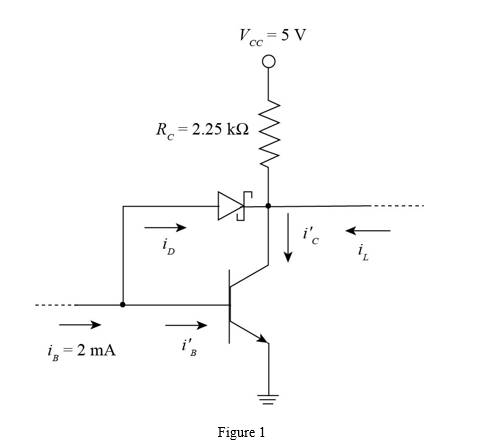
Apply KVL in the above circuit.
Substitute
The expression for the value of the current
Substitute
The expression for the value of the base current
Substitute
The expression for the value of the drain current is given by,
Substitute
(b)
The value of the current
(b)
Answer to Problem 17.11EP
The value of the current
Explanation of Solution
Calculation:
Apply KVL in the above circuit.
Substitute
The expression for the value of the current
The expression for the value of the current
The expression for the value of the current
From equation (2) and equation (3), the value of the current
Substitute
Substitute
Substitute
Substitute
The expression for the value of the drain current is given by,
Substitute
Conclusion:
Therefore, the value of the current
(c)
The value of the maximum load current.
(c)
Answer to Problem 17.11EP
The maximum value of the load current is
Explanation of Solution
Calculation:
The expression for the value of the
Substitute
The expression for condition of the edge saturation is given by,
Substitute
Substitute
The expression for the value of the load current is given by,
Substitute
Conclusion:
Therefore, the maximum value of the load current is
Want to see more full solutions like this?
Chapter 17 Solutions
Microelectronics: Circuit Analysis and Design


- What is the main disadvantage of linear delta modulation? What is the solution for this problem? this question from digital communication course.arrow_forwardState the advantages and disadvantages of theDSB_LCarrow_forwardIn the figure below, an x(t) signal varying between +- 1.6 V is split into 8 quanta levels and converted to a digital signal. being converted. a) Calculate the quantization gap voltage (step)? b) Draw the PAM, PCM and ASK outputs in this conversion process? c) Calculate bit transmission rate if sampling pulse frequency ?? = 2kHz.arrow_forward
- Draw the schematic of a three-input NAND gate. What are the W/L ratios for thetransistors based?arrow_forwardExplain with the aid of equations the following: How to improve the SNqR in the PCM system?arrow_forward15. How many OC signals are used in a SONET network with a 622.08 Mbps line rate?A. 8064B. 4C. 12D. 8arrow_forward
- 2/ a communications channel of 5 MHz. Determine the maximum transmission rate possible with an 8-PSK modulator considering a unit fall factor (R = 1). Compare it with the Maximum transmission rate of a QPSK modulator with the same fall factor. Which Modulator would you recommend and why?arrow_forward7. The advantage of a differential phase-shift keying (DPSK) system is that_____________ is (are) not required.A. carrier synchronizerB. voltage-controlled oscillatorsC. upper and lower sidebandsD. carrier recovery circuitryarrow_forwardThe number of bits per sample in a PCM system has SNqR=45 dB is?arrow_forward
- Explain the QPSK modulation challenges and problems.arrow_forwardHow might one determine general-direction MTF (modulation transfer function) to determine if there are any angular sensitivities to a camera system?arrow_forward7. Sketch the transfer characteristics of a n-channel depletion-type MOSFET if Vp= -5V and IDSS =10mAarrow_forward
 Introductory Circuit Analysis (13th Edition)Electrical EngineeringISBN:9780133923605Author:Robert L. BoylestadPublisher:PEARSON
 Delmar's Standard Textbook Of ElectricityElectrical EngineeringISBN:9781337900348Author:Stephen L. HermanPublisher:Cengage Learning
 Programmable Logic ControllersElectrical EngineeringISBN:9780073373843Author:Frank D. PetruzellaPublisher:McGraw-Hill Education
 Fundamentals of Electric CircuitsElectrical EngineeringISBN:9780078028229Author:Charles K Alexander, Matthew SadikuPublisher:McGraw-Hill Education
 Electric Circuits. (11th Edition)Electrical EngineeringISBN:9780134746968Author:James W. Nilsson, Susan RiedelPublisher:PEARSON
 Engineering ElectromagneticsElectrical EngineeringISBN:9780078028151Author:Hayt, William H. (william Hart), Jr, BUCK, John A.Publisher:Mcgraw-hill Education,