APPLIED STATICS & STRENGTH OF MATERIALS
null Edition
ISBN: 9781323905210
Author: Limbrunner
Publisher: PEARSON C
bartleby

Concept explainers

bartleby

Videos

Question
Book Icon
Chapter 17, Problem 17.1P
To determine

The stresses at the corners of the cross-section of given (S4S) timber beam at the point of maximum moment.

Expert Solution & Answer
Check Mark

Explanation of Solution

Given information:

For the given 100mm by 100mm timber beam, we have a diagram as below:

APPLIED STATICS & STRENGTH OF MATERIALS, Chapter 17, Problem 17.1P , additional homework tip  1

We have following data,
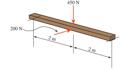
Given beam is 100mm by 100mm timber

a = 100mm ×|1 m103 mm|

Total length of the beam, L=4m

Point loads acting of the beam, Px=200N and Py=450N

For the given beam, we have free body a diagram as below:

APPLIED STATICS & STRENGTH OF MATERIALS, Chapter 17, Problem 17.1P , additional homework tip  2

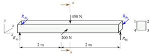
We know that if the point loads are acting over the center of the simply supported beam then the maximum bending moment occurs at the mid span of it.

So the maximum moment at the mid span about x-axis would be,

Mx=Py×L4Mx=450×44Mx=450 N-m

In the same manner, the maximum moment at the mid span about y-axis is,

My=Px×L4My=200×44My=200 N-m

For the cross-section of the beam, we know that the second moment of inertia about centroidal x and y axes must be same. This can be determined as follow:

  Ix=a412Ix=[ 100×|1/ 10 3|]412 (Substituting value of a =100mm×|1m/103mm|Ix=8.333×106 m4

We can obtain bending stress by use of below mentioned equation:

s=±MxyIx±MyxIys=±Mx(a/2)Ix±My(a/2)Iy

In the above equation, putting values,

s=±Mx(a/2)Ix±My(a/2)Iys=±450( [100×|1/ 103 |]/2)8.333×106±200( [100×|1/ 103 |]/2)8.333×106s=±2700108±1200048 N/m2s±2.7±1.2 MPa

Finally calculating the stress at points 1,2 , 3 and 4.

s1=2.71.2s1=3.9 MPas2=2.7+1.2s2=1.5 MPa;s3=+2.7+1.2s3=3.9 MPa;s4=+2.71.2s4=+1.5 MPa

Conclusion:

The stresses at the corners of the cross-section of given (S4S) timber beam are 3.9 MPa , 1.5 MPa , 3.9 MPa and +1.5 MPa at the point of maximum moment.

Want to see more full solutions like this?

Subscribe now to access step-by-step solutions to millions of textbook problems written by subject matter experts!

Chapter 17 Solutions

APPLIED STATICS & STRENGTH OF MATERIALS

Ch. 17 - A concrete pedestal is in the shape of a cube and...Ch. 17 - 17.12 For the pedestal of Problem 17.11, assume...Ch. 17 - 17.13 Rework Problem 17.11, but assume that the...Ch. 17 - A 12-in-square concrete pedestal is subjected to a...Ch. 17 - 17.15 A short compression member is subjected to a...Ch. 17 - A rectangular concrete footing, 4 ft by 8 ft in...Ch. 17 - The bending and shear stresses developed at a...Ch. 17 - Stresses developed at a point in a machine part...Ch. 17 - Calculate the principal stresses at points A and B...Ch. 17 - 17.20 Rework Problem 17.19 using P = 8000 lb and...Ch. 17 - 17.21 A 1-in.-square steel bar is subjected to an...Ch. 17 - 17.22 A bar having a cross-sectional area of 6...Ch. 17 - Rework Problem 17.22, changing the load to a...Ch. 17 - Solve Problem l7.17 using Mohr’s circle.Ch. 17 - For the elements shown in Problem 17.18, use...Ch. 17 - Solve Problem 17.19 using Mohr’s circle.Ch. 17 - In Problem 17.19, change the load to 8000 lb and...Ch. 17 - For the following computer problems, any...Ch. 17 - For the following computer problems, any...Ch. 17 - For the following computer problems, any...Ch. 17 - For the following computer problems, any...Ch. 17 - A 4-in.-by-8-in. (S4S) Douglas fir timber beam is...Ch. 17 - A horizontal flexural member (a girt) in the wall...Ch. 17 - A simply supported W1850 structural steel...Ch. 17 - A steel link in a machine is designed to avoid...Ch. 17 - 17.36 An 8-in-square (S4S) vertical timber post is...Ch. 17 - A short 3-in.-square steel bar with a...Ch. 17 - A timber member 150 mm by 250 mm (S4S) is loaded...Ch. 17 - A concrete wall 8 ft high and 3 ft thick is...Ch. 17 - 17.40 A short compression member is subjected to a...Ch. 17 - 17.41 Calculate the maximum eccentric load that...Ch. 17 - A short compression member is subjected to two...Ch. 17 - 17.43 Calculate the force P that may be applied to...Ch. 17 - 17.44 A load of 1000 lb is supported on a...Ch. 17 - 17.45 A short compression member is subjected to...Ch. 17 - 17.46 A structural steel wide-flange section is...Ch. 17 - 17.47 A cast-iron frame for a piece of industrial...Ch. 17 - 17.48 The assembly shown is used in a machine. It...Ch. 17 - 17.49 A 50-mm-diameter solid steel shaft is...Ch. 17 - An element of a machine member is subjected to the...Ch. 17 - 17.51 A short-span cantilever built-up beam has...Ch. 17 - Solve Problem 17.50 using Mohr’s circle.Ch. 17 - 17.53 A cantilever beam is subjected to an...Ch. 17 - A 6-in.-diameter solid shaft is subjected to a...Ch. 17 - Rework parts (b) and (c) of Example 17.7 using...
Knowledge Booster
Background pattern image
Mechanical Engineering
Learn more about
Need a deep-dive on the concept behind this application? Look no further. Learn more about this topic, mechanical-engineering and related others by exploring similar questions and additional content below.
Recommended textbooks for you
Text book image
Elements Of Electromagnetics
Mechanical Engineering
ISBN:9780190698614
Author:Sadiku, Matthew N. O.
Publisher:Oxford University Press
Text book image
Mechanics of Materials (10th Edition)
Mechanical Engineering
ISBN:9780134319650
Author:Russell C. Hibbeler
Publisher:PEARSON
Text book image
Thermodynamics: An Engineering Approach
Mechanical Engineering
ISBN:9781259822674
Author:Yunus A. Cengel Dr., Michael A. Boles
Publisher:McGraw-Hill Education
Text book image
Control Systems Engineering
Mechanical Engineering
ISBN:9781118170519
Author:Norman S. Nise
Publisher:WILEY
Text book image
Mechanics of Materials (MindTap Course List)
Mechanical Engineering
ISBN:9781337093347
Author:Barry J. Goodno, James M. Gere
Publisher:Cengage Learning
Text book image
Engineering Mechanics: Statics
Mechanical Engineering
ISBN:9781118807330
Author:James L. Meriam, L. G. Kraige, J. N. Bolton
Publisher:WILEY
Everything About COMBINED LOADING in 10 Minutes! Mechanics of Materials; Author: Less Boring Lectures;https://www.youtube.com/watch?v=N-PlI900hSg;License: Standard youtube license