
Concept explainers
Videos
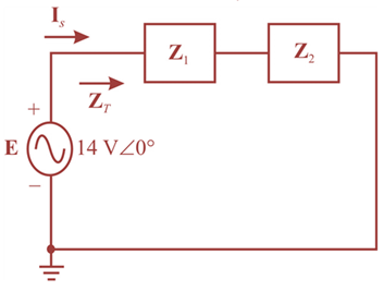
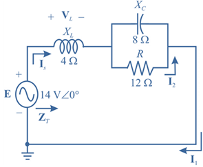
For theseries-parallel network in Fig.17.38.
a. Calculate ZT.
b. Determine Is.
c. Determine I1.
d. Find I2.
e. Find VL..

Fig.17.38
(a)
Total impedance
Answer to Problem 1P
Explanation of Solution
Given:
The given circuit is:
Calculation:
Let us modify the circuit as below to calculate the total impedance.
In the modified diagram,
Impedance
Impedance
Therefore, total impedance will be:
Putting the values for the total impedance:
(b)
The current
Answer to Problem 1P
Explanation of Solution
Given:
The given circuit is:

Calculation:
Let us modify the circuit as below to calculate the total impedance.

In the modified diagram,
Impedance
Impedance
Current
(c)
The current
Answer to Problem 1P
Explanation of Solution
Given:
The given circuit is:

Calculation:
Let us modify the circuit as below to calculate the total impedance.

In the modified diagram,
Impedance
Impedance
Current
We can see from the circuit that,
(d)
The current
Answer to Problem 1P
Explanation of Solution
Given:
The given circuit is:
Calculation:
Let us modify the circuit as below to calculate the total impedance.

In the modified diagram,
Impedance
Impedance
Current
(e)
Voltage
Answer to Problem 1P
Explanation of Solution
Given:
The given circuit is:

Calculation:
Let us modify the circuit as below to calculate the total impedance.

In the modified diagram,
Impedance
Impedance
Voltage
Want to see more full solutions like this?
Chapter 17 Solutions
Introductory Circuit Analysis; Laboratory Manual For Introductory Circuit Analysis Format: Kit/package/shrinkwrap
Additional Engineering Textbook Solutions
Electric Circuits (10th Edition)
Principles Of Electric Circuits
Electrical Engineering: Principles & Applications (7th Edition)
Loose Leaf for Engineering Circuit Analysis Format: Loose-leaf
Fundamentals of Electric Circuits
Basic Engineering Circuit Analysis


- help with this AC Analysis problem ASAP TYIAarrow_forwardThe initals "Am" stand for amplitude modulation. Insted of fluctuating frequenices as above, they instead vary the amplitude, such that Y= A(t) sin [2pief]t. Notice that the frequency is now fixed, but the amplitude will be inconsistent. Each AM station is assigned a frequency in KHz (1,000 waves/second.) For example, 760AM is assigned a frequency of f=760kHz. What is the wavelength of the 760AM radio waves? Sketch of graph of y=2(exponent t) sin(t) and explain graphically what the amplitude is doing. The Bay of Fundy is between Maine and Nova Scotia, and it is famous for its high tides. There is a dock such that the water is 2ft deep at low tide and 58ft deep at high tide. High tide occurs 6 hours and 12 minutes after low tide. Draw a graph and create the equation that models that depth of water nd a function of time after high tide has occurred.arrow_forwardShow that VSWR for a transmission line will have values between 1 and infinity.arrow_forward
- The ERP of a transmitting station is specified as 17W in a given direction. Express this as an EIRP in dBm.arrow_forwardFor an AM Radio channel, calculate the power efficiency of a system when the carrierroot-mean-square voltage is √20 V and the modulation index is 50%.arrow_forwardCt-2(17.31)arrow_forward
- Q3 / A test signal ( sine wave 20kHz , 3V ) is used to modulate a carrier sinusoidal signal ( 1MHz , 7V ) using an AM - DSB LC system . calculate : ( a ) the total output power that would be delivered to the 550 antenna , ( b ) the USB power , ( c )transmission efficiencyarrow_forwardThe noise coefficient of a microwave receiver front section is desired to be measured by the Y-factor method. Using a noise source with an extreme power rating (ENR) of 23 dB and a liquid nitrogen cold load (77 °K), the Y-factor ratio is measured to be 14.83dB. Find the noise coefficient of the receiverarrow_forwardlet studend id is: 19.01.08.085 where abc is : 085arrow_forward
- A 3m coax transmission line used for transmission of a 3Ghz signal, has a characteristic impedance of 120 ohms. The dielectric in the line has a relative permittivity of 2.75. If the line is terminated in a load impedance of 75-j150 ohms, determine the impedance at the sending end. Show complete solutionarrow_forwardIn an AM transmission system the transmitter current was found to be 9.A. If the carrier signal is the only one to be sent and later increases to 10.72 A. Also if the carrier is modulated by a single sinusoidal wave, compute the percentage modulation. Again find the current of the antenna if the percentage of modulation changes 85%.arrow_forwardA planar LED is fabricated from gallium arsenide which has a refractive indexof 3.6. Calculate the optical power emitted into air as a percentage of theinternal optical power for the device when the transmission factor at thecrystal–air interface is 0.68. When the optical power generated internally is 50% of the electric powersupplied, determine the external power efficiency.arrow_forward
 Introductory Circuit Analysis (13th Edition)Electrical EngineeringISBN:9780133923605Author:Robert L. BoylestadPublisher:PEARSON
 Delmar's Standard Textbook Of ElectricityElectrical EngineeringISBN:9781337900348Author:Stephen L. HermanPublisher:Cengage Learning
 Programmable Logic ControllersElectrical EngineeringISBN:9780073373843Author:Frank D. PetruzellaPublisher:McGraw-Hill Education
 Fundamentals of Electric CircuitsElectrical EngineeringISBN:9780078028229Author:Charles K Alexander, Matthew SadikuPublisher:McGraw-Hill Education
 Electric Circuits. (11th Edition)Electrical EngineeringISBN:9780134746968Author:James W. Nilsson, Susan RiedelPublisher:PEARSON
 Engineering ElectromagneticsElectrical EngineeringISBN:9780078028151Author:Hayt, William H. (william Hart), Jr, BUCK, John A.Publisher:Mcgraw-hill Education,