
Concept explainers
Videos
The uniform rectangular block shown is moving along a frictionless surface with a velocity
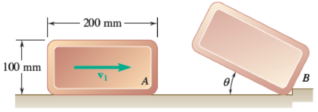
Fig. P17.115
Find the magnitude of the velocity
Answer to Problem 17.115P
The magnitude of the velocity
Explanation of Solution
Given information:
The length
The width
Calculation:
Write the equation of centroidal moment of inertia
Find the one half of the diagonal distance
Substitute 200 mm for a and 100 mm for b.
Before impact, let
Here, magnitude of velocity of the rectangular block is
After impact, the rectangular block rotates about small obstruction at B. Therefore,
Let
Find the equation of velocity
Consider the principle of impulse and momentum.
Sketch the impulse and momentum diagram of the rectangular block as shown in Figure (1).
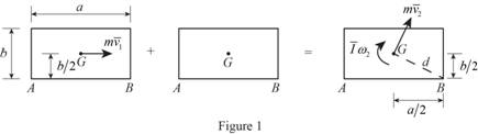
Take moment about B (positive sign in clockwise direction).
Substitute
Substitute
Sketch the free body diagram of the rectangular block after impact (position 2) and final position (position 3) as shown in Figure (2).
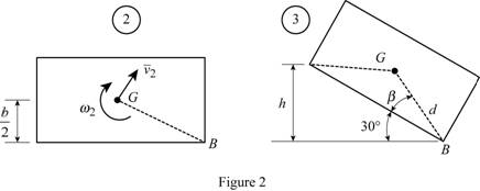
Write the equation of velocity
Refer Figure (2),
Find the angle
Substitute 200 mm for a and 100 mm for b.
Find the distance (h).
Substitute 0.1118 m for d and
At position 3, the angular velocity
Write the equation of the potential energy
Write the equation of the kinetic energy
Substitute
Substitute
Write the equation of the potential energy
The kinetic energy of the system at final position
Consider the conservation of energy.
Substitute
Substitute 200 mm for a, 100 mm for b, 0.1118 m for d,
Find the the magnitude of the velocity
Substitute 200 mm for a, 100 mm for b, and
Thus, the magnitude of the velocity
Want to see more full solutions like this?
Chapter 17 Solutions
Vector Mechanics for Engineers: Statics and Dynamics
Additional Engineering Textbook Solutions
Introduction to Heat Transfer
Engineering Mechanics: Statics
EBK FUNDAMENTALS OF THERMODYNAMICS, ENH
Automotive Technology: Principles, Diagnosis, and Service (5th Edition)
Vector Mechanics for Engineers: Statics, 11th Edition
Engineering Mechanics: Statics


- A square plate of side a and mass m supported by a ball-and-socket joint at A is rotating about the y axis with a constant angular velocity ω = ω 0 j when an obstruction is suddenly introduced at B in the xy plane. Assuming the impact at B to be perfectly plastic (e = 0), determine immediately after the impact (a ) the angular velocity of the plate, (b ) the velocity of its mass center G.arrow_forwardA 3-kg bar AB is attached by a pin at D to a 4-kg square plate, which can rotate freely about a vertical axis. Knowing that the angular velocity of the plate is 120 rpm when the bar is vertical, determine (a ) the angular velocity of the plate after the bar has swung into a horizontal position and has come to rest against pin C, (b) the energy lost during the plastic impact at C.arrow_forwardA bowler projects an 8-in.-diameter ball weighing 12 lb along an alley with a forward velocity v0 of 15 ft/s and a backspin ω0 of 9 rad/s. Knowing that the coefficient of kinetic friction between the ball and the alley is 0.10, determine (a) the time t1 at which the ball will start rolling without sliding, (b) the speed of the ball at time t1, (c) the distance the ball will have traveled at time t1arrow_forward
- Two identical giant flywheels are on 2 identical slopes at an angle alpha = 20 deg. One flywheel is rolling on its inside shaft of diameter d1 = 3 ft, and the second flywheel is rolling without slipping on its outside diameter d2 = 5 ft. They are both released from rest. The weight of the flywheel is W = 8 lbs Knowing that flywheel 1 attains a speed of v = 7.0 ft/s in t = [t] s, (if t doesn't show take any t between 5 and 10 sec) find the radius of gyration of the flywheels, following those steps: b. Find omega final c. Find the angular impulse at the point of contact between the shaft and the slope. d. Write the formula to find the final momentum. e. Solve for k, using the principle of angular impulse and momentumarrow_forwardThe double pulley shown has a mass of 15 kg and a centroidal radius of gyration of 160 mm. Cylinder A and block B are attached to cords that are wrapped on the pulleys as shown. The coefficient of kinetic friction between block and the surface is 0.2. Knowing that the system is at rest in the position shown when a constant force P = 200 N is applied to cylinder A , determine (a ) the velocity of cylinder A as it strikes the ground, (b ) the total distance that block B moves before coming to rest.arrow_forwardTwo identical giant flywheels are on 2 identical slopes at an angle alpha = 20 deg. One flywheel is rolling on its inside shaft of diameter d1 = 3 ft, and the second flywheel is rolling without slipping on its outside diameter d2 = 5 ft. They are both released from rest. The weight of the flywheel is W = 8 lbs 1. Knowing that flywheel 1 attains a speed of v = 7.0 ft/s in t = [t] s, (if t doesn't show take any t between 5 and 10 sec) find the radius of gyration of the flywheels, following those steps: 3. What will be the distance between the 2 flywheels? Which one is in front? a. Explain your strategy to find the distance made by each wheel. b. Find the 3 distances made by each wheel. c. Find the distance between the 2 flywheels. d. Why one is in front? 4. Using flywheel 2, what is the coefficient of static friction between the outside diameter and the ground required to prevent slipping? a. Using the 3 previous diagrams, which impulse will you consider finding the force of…arrow_forward
- A long ladder of length l, mass m, and centroidal mass moment of inertia I is placed against a house at an angle 0=0O. Knowing that the ladder is released from rest, determine the angular velocity of the ladder when 0=02. Assume the ladder can slide freely on the horizontal ground and on the vertical wall.arrow_forwardThe mechanism shown is one of two identical mechanisms attached to the two sides of a 200-lb uniform rectangular door. Edge ABC of the door is guided by wheels of negligible mass that roll in horizontal and vertical tracks. A spring with a constant of k = 40 lb/ft is attached to wheel B. Knowing that the door is released from rest in the position 0= 30° with the spring unstretched, determine the velocity of wheel A just as the door reaches the vertical position.arrow_forwardThe mechanism shown is one of two identical mechanisms attached to the two sides of a 200-lb uniform rectangular door. Edge ABC of the door is guided by wheels of negligible mass that roll in horizontal and vertical tracks. A spring with a constant k is attached to wheel B in such a way that its tension is zero when 0 = 30°, Knowing that the door is released from rest in the position 0 = 45° and reaches the vertical position with an angular velocity of 0.6 rad/s, determine the spring constant k.arrow_forward
- A thin circular rod is supported in a vertical plane by a bracket at A. Attached to the bracket and loosely wound around the rod is a spring of constant k= 3 lb/ft and undeformed length equal to the arc of circle AB. An 8-oz collar C , not attached to the spring, can slide without friction along the rod. Knowing that the collar is released from rest at an angle 0 with the vertical, determine (a) the smallest value of 0 for which the collar will pass through D and reach point A, (b) the velocity of the collar as it reaches point A.arrow_forwardA 48-kg advertising panel of length 2a = 2.4 m and width 2b = 1.6 m is kept rotating at a constant rate w1 about its horizontal axis by a small electric motor attached at A to frame ACB. This frame itself is kept rotating at a constant rate w2 about a vertical axis by a second motor attached at C to the column CD. Knowing that the panel and the frame complete a full revolution in 6 s and 12 s, respectively, express, as a function of the angle 0, the dynamic reaction exerted on column CD by its support at D.arrow_forwardTwo disks A and B, of mass m 1 kg each and of radius 10 cm, are placed on a horizontal table. The disk A is launched in translation with a speed of 10 m/s along the y axis, B is at rest. The coefficient of kinetic friction between the disks is 0.5. The line of impact is at an angle of 60° with the x-axis. The moment of inertia of each disk around its center of mass is I = 1₂ = 0.005 kg.m². The coefficient of restitution between the two disks is e=0.6. a) Determine the velocities of the centers of the two disks, just after the impact. b) Calculate the angular velocities of the disks, just after the impact. c) Calculate the energy loss during the impact.arrow_forward
 Elements Of ElectromagneticsMechanical EngineeringISBN:9780190698614Author:Sadiku, Matthew N. O.Publisher:Oxford University Press
 Mechanics of Materials (10th Edition)Mechanical EngineeringISBN:9780134319650Author:Russell C. HibbelerPublisher:PEARSON
 Thermodynamics: An Engineering ApproachMechanical EngineeringISBN:9781259822674Author:Yunus A. Cengel Dr., Michael A. BolesPublisher:McGraw-Hill Education
 Control Systems EngineeringMechanical EngineeringISBN:9781118170519Author:Norman S. NisePublisher:WILEY
 Mechanics of Materials (MindTap Course List)Mechanical EngineeringISBN:9781337093347Author:Barry J. Goodno, James M. GerePublisher:Cengage Learning
 Engineering Mechanics: StaticsMechanical EngineeringISBN:9781118807330Author:James L. Meriam, L. G. Kraige, J. N. BoltonPublisher:WILEY