
Concept explainers
Videos
Three 25-lb rotor disks are attached to a shaft that rotates at 720 rpm. Disk A is attached eccentrically so that its mass center is
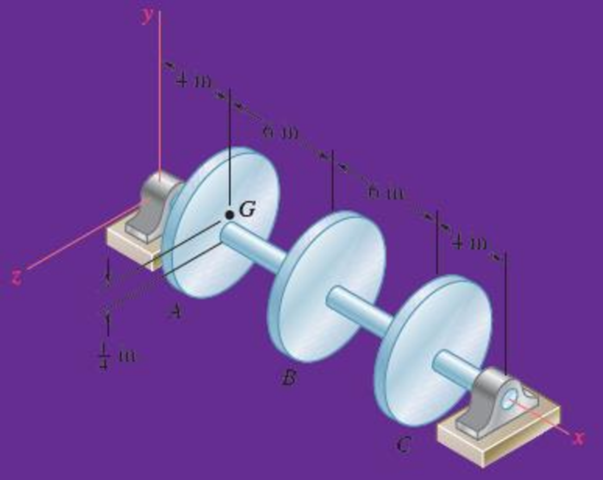
Fig. P18.147
Where should 2 lb weights be bolted to disks B and C to balance the system dynamically.
Answer to Problem 18.147RP
The 2 lb weights be bolted to disks B and C to balance the system dynamically are
Explanation of Solution
Given Information:
The weight (W) of the disk is 25 lb.
The shaft rotates at 720 rpm.
The mass center of the disk A is
Calculation:
Draw the free body diagram of the system as shown in Figure (1).
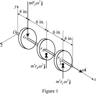
The angular velocity of the shaft is constant. So, the rate of change of angular momentum is zero.
Express the effective force
Here,
Express the effective force
Express the effective force
The sum of the effective forces of the discs should be equal to zero for the system to be in dynamic balance.
Substitute
Substitute
According to principle of impulse momentum, the total momentum is zero.
Express the moment about O:
Here,
Substitute
Substitute
Multiply Equation (1) by
The 2 lb weight is be placed above the shaft for disk C.
Substitute
The 2 lb weight is be placed below the shaft for disk B.
Thus, the 2 lb weights be bolted to disks B and C to balance the system dynamically are
Want to see more full solutions like this?
Chapter 18 Solutions
Vector Mechanics for Engineers: Statics and Dynamics


- The 10-in.-radius brake drum is attached to a larger flywheel which is not shown. The total mass moment of inertia of the flywheel and drum is 22 lb ⋅ ft ⋅ s 2 and the coefficient of kinetic friction between the drum and the brake shoe is 0.41. Knowing that the initial angular velocity is 255 rpm clockwise, determine the force which must be exerted by the hydraulic cylinder at point B if the system is to stop in 85 revolutions. DO NOT ROUND OFF IN THE SOLUTION. ROUND OFF ONLY THE FINAL ANSWERarrow_forwardA long ladder of length l, mass m, and centroidal mass moment of inertia I is placed against a house at an angle 0=0O. Knowing that the ladder is released from rest, determine the angular velocity of the ladder when 0=02. Assume the ladder can slide freely on the horizontal ground and on the vertical wall.arrow_forwardA loaded porter governor has four links each of 250mm long.two revolving masses each of 3kg and a central dead weight of mass 20kg .all the links are attached to respective sleeves at a distance of 40mm from the axis of rotation.the masses revolve at a radius of 150 mm at minimum speed and at a radius of 200mm at maximum speed , Determine the range of speedarrow_forward
- The 8-in. radius brake drum is attached to a larger flywheel that is not shown. The total mass moment of inertia of the drum and the flywheel is 15 lb.ft.s2 and the coefficient of kinetic friction between the drum and the brake shoe is 0.40. Knowing that the angular velocity of the flywheel is 450 rpm clockwise when a force P of magnitude 65 lbf. is applied to the pedal C, determine the number of the revolutions executed by the flywheel before it comes to rest. (The final answer should be in two decimal places with correct units)arrow_forwardA cylinder of radius r and weight W with an initial counterclockwise angular velocity w0 is placed in the corner formed by the floor and a vertical wall. Denoting by μk the coefficient of kinetic friction between the cylinder and the wall and the floor, derive an expression for the time required for the cylinder to come to rest.arrow_forwardThe shutter shown was formed by removing one quarter of a disk of 0.75-in. radius and is used to interrupt a beam of light emanating from a lens at C. Knowing that the shutter weighs 0.125 lb and rotates at the constant rate of 24 cycles per second, determine the magnitude of the force exerted by the shutter on the shaft at Aarrow_forward
- In order to determine the mass moment of inertia of a flywheel of radius 600 mm, a 12-kg block is attached to a wire that is wrapped around the flywheel. The block is released and is observed to fall 3 m in 4.6 s. To eliminate bearing friction from the computation, a second block of mass 24 kg is used and is observed to fall 3 m in 3.1 s. Assuming that the moment of the couple due to friction remains constant, determine the mass moment of inertia of the flywheel.arrow_forwardA 48-kg advertising panel of length 2a = 2.4 m and width 2b = 1.6 m is kept rotating at a constant rate w1 about its horizontal axis by a small electric motor attached at A to frame ACB. This frame itself is kept rotating at a constant rate w2 about a vertical axis by a second motor attached at C to the column CD. Knowing that the panel and the frame complete a full revolution in 6 s and 12 s, respectively, express, as a function of the angle 0, the dynamic reaction exerted on column CD by its support at D.arrow_forwardA 240-lb block is suspended from an inextensible cable which is wrapped around a drum of 1.25-ft radius rigidly attached to a flywheel. The drum and flywheel have a combined centroidal moment of intertia of 10.5 lb-ft-s^2. At the instant shown, the velocity of the block is 6 ft/s directed downward. The bearing at A as a frictional moment of 60 lb-ft. What is the kinetic energy of the system after the block moved after 4ft? (in ft-lb)arrow_forward
- A 255-lbf block is suspended from an inextensible cable which is wrapped around a drum of 1.75-ft radius rigidly attached to a flywheel. The drum and flywheel have a combined centroidal moment of inertia 12 lb . ft . s 2 . At the instant shown, the velocity of the block is unknown directed downward. Knowing that the bearing at A is poorly lubricated and that the bearing friction is equivalent to a couple M of magnitude 65 lb .ft, determine the velocity of the block before it has moved 3.5 ft downward if at S2 speed is 13.5ft/sarrow_forwardA 1.6-kg tube AB can slide freely on rod DE which in turn can rotate freely in a horizontal plane. Initially the assembly is rotating with an angular velocity of magnitude w = 5 rad/s and the tube is held in position by a cord. The moment of inertia of the rod and bracket about the vertical axis of rotation is 0.30 kg.m2 and the centroidal moment of inertia of the tube about a vertical axis is 0.0025 kg.m2If the cord suddenly breaks, determine (a) the angular velocity of the assembly after the tube has moved to end E, (b) the energy lost during the plastic impact at E.arrow_forwardA wheel of radius r and centroidal radius of gyration k is released from rest on the incline shown at time t = 0. Assuming that the wheel rolls without sliding, determine (a) the velocity of its center at time t, (b) the coefficient of static friction required to prevent slipping.arrow_forward
 Elements Of ElectromagneticsMechanical EngineeringISBN:9780190698614Author:Sadiku, Matthew N. O.Publisher:Oxford University Press
 Mechanics of Materials (10th Edition)Mechanical EngineeringISBN:9780134319650Author:Russell C. HibbelerPublisher:PEARSON
 Thermodynamics: An Engineering ApproachMechanical EngineeringISBN:9781259822674Author:Yunus A. Cengel Dr., Michael A. BolesPublisher:McGraw-Hill Education
 Control Systems EngineeringMechanical EngineeringISBN:9781118170519Author:Norman S. NisePublisher:WILEY
 Mechanics of Materials (MindTap Course List)Mechanical EngineeringISBN:9781337093347Author:Barry J. Goodno, James M. GerePublisher:Cengage Learning
 Engineering Mechanics: StaticsMechanical EngineeringISBN:9781118807330Author:James L. Meriam, L. G. Kraige, J. N. BoltonPublisher:WILEY