
Concept explainers
Videos
Draw a control circuit with no-voltage protection. Describe how this method of wiring protects the machine operator.
Draw a control circuit with no-voltage protection and describe how this method of wiring protects the machine operator.
Explanation of Solution
The three wire control circuit uses start-stop stations, momentary contact, and holding circuit interlock connected in a parallel form with the start pushbutton in order to maintain the circuit. The no-voltage protection can be obtained using the three wire control circuit. The control circuit with no-voltage protection is drawn as Figure 1.
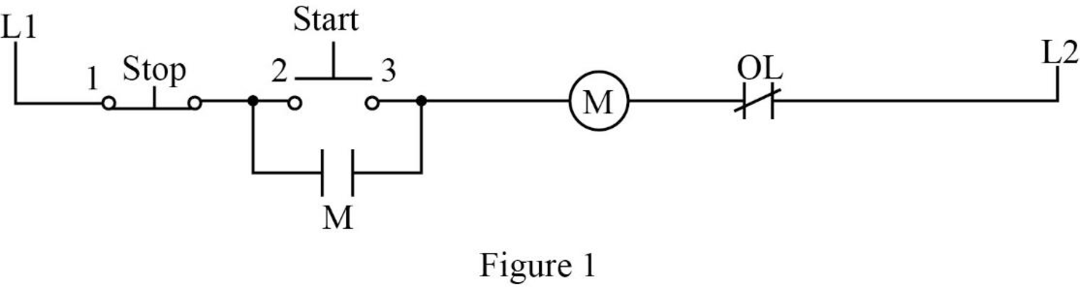
In Figure 1, when the start pushbutton is pressed, the control circuit can be completed using coil M and closes all the M contacts. It leads to close the motor connection to the line by contacting the power circuits to the motor. The auxiliary contact M, which is connected in parallel with the start pushbutton, is also closed. This M contact is used to maintain the circuit to coil M when the start pushbutton is released. Such a contact is called as holding or sealing or maintaining contact.
When the stop pushbutton is pressed, the circuit brakes and opens the contact M. After releasing the stop pushbutton, the circuit remains the same because the start pushbutton and holding contact is in the open state. In order to complete the circuit, the start pushbutton should be pressed again.
If the supply voltage of the circuit fails, it could lead to de-energize the circuit. When the power or supply voltage is restored, the circuit remains in the open state until the start pushbutton is pressed manually. Therefore, this arrangement is called as no-voltage protection and such an arrangement is used to protect both the operator and the equipment.
Conclusion:
Thus, the control circuit with no-voltage protection is drawn and the working process is explained.
Want to see more full solutions like this?
Chapter 18 Solutions
Electric Motor Control


- What is a control circuit?arrow_forwardWhy are series circuits used for most control circuits?arrow_forwardWhen reading a schematic diagram, are the control components shown as they should be when the machine is turned off or de-energized, or are they shown as they should be when the machine is in operation?arrow_forward
- Why is it important to understand the purpose and action of the total operational system when working with controls?arrow_forwardConvert the control circuit only, Figure 2111, from the wiring diagram to an elementary diagram. Include the limit switches (RLS, FLS) as operating in the control circuit.arrow_forwardHow can you safeguard your machine against potential dangers like power outages?arrow_forward
- Q about Control Systems. Looking for only SECOND question's answerarrow_forwardGive 5 examples of Open-loop controlled systems and 5 Closed-loop control systems found at home and draw the block diagram for each one.arrow_forwardHello Sir.Good Evening. I have a question in my home work related Control System Lesson. The following below is my question.Please advise, Thank you so much. "Give a control mechanical system and show how to get a transfer function of the system"arrow_forward
- What precautions can you take to ensure that your machine is protected from things like power outages?arrow_forwardExplain the meaning of CASCADE Control system (Serie ). a.Give a practical example of this Cascade control APP on board? b.Make a Circuit sketch of the control ? c.Explain how it works,please ?arrow_forwardWhat is a bus controller?arrow_forward

 Electricity for Refrigeration, Heating, and Air C...Mechanical EngineeringISBN:9781337399128Author:Russell E. SmithPublisher:Cengage Learning