
College Physics
11th Edition
ISBN: 9781305952300
Author: Raymond A. Serway, Chris Vuille
Publisher: Cengage Learning
expand_more
expand_more
format_list_bulleted
Videos
Textbook Question
Chapter 18, Problem 35P
Consider a series RC circuit as in Figure P18.35 for which R = 1.00 MΩ, C = 5.00 µF, and ε = 30.0 V. Find (a) the time constant of the circuit and (b) the maximum charge on the capacitor after the switch is thrown closed. (c) Find the current in the resistor 10.0 s after the switch is closed.
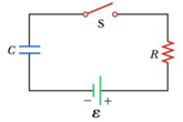
Figure P18.35 Problem 35 and 38.
Expert Solution & Answer

Trending nowThis is a popular solution!

Chapter 18 Solutions
College Physics
Ch. 18.1 - True or False: While discharging, the terminal...Ch. 18.1 - Why does a battery get warm while in use?Ch. 18.2 - In Figure 18.5, the current is measured with the...Ch. 18.2 - The circuit in Figure 18.5 consists of two...Ch. 18.3 - In Figure 18.8, the current is measured with the...Ch. 18.3 - When the switch is open in Figure 18.8, power Po...Ch. 18.3 - Suppose you have three identical lightbulbs, some...Ch. 18.3 - If the lightbulbs in Quick Quiz 18.7 are connected...Ch. 18.5 - The switch is closed in Figure 18.20. After a long...Ch. 18 - Choose the words that make each statement correct....
Ch. 18 - Given three lightbulbs and a battery, sketch as...Ch. 18 - Suppose the energy transferred to a dead battery...Ch. 18 - A short circuit is a circuit containing a path of...Ch. 18 - Electric current I enters a node with three...Ch. 18 - If electrical power is transmitted over long...Ch. 18 - The following statements are related to household...Ch. 18 - Two sets of Christmas lights are available. For...Ch. 18 - Why is it possible for a bird to sit on a...Ch. 18 - An uncharged series RC circuit is to be connected...Ch. 18 - Suppose a parachutist lands on a high-voltage wire...Ch. 18 - A ski resort consists of a few chairlifts and...Ch. 18 - Embodied in Kirchhoffs rules are two conservation...Ch. 18 - Why is it dangerous to turn on a light when you...Ch. 18 - A battery haring an emf of 9.00 V delivers 117 mA...Ch. 18 - Prob. 2PCh. 18 - A battery with an emf of 12.0 V has a terminal...Ch. 18 - A battery with a 0.100- internal resistance...Ch. 18 - Two resistors, R1 and R2 are connected in series....Ch. 18 - Three 9.0- resistors are connected in series with...Ch. 18 - (a) Find the equivalent resistance between points...Ch. 18 - Consider the combination of resistors shown in...Ch. 18 - Prob. 9PCh. 18 - Consider the circuit shown in Figure P18.10. (a)...Ch. 18 - Consider the circuit shown in Figure P18.11. Find...Ch. 18 - Four resistors are connected to a battery as shown...Ch. 18 - The resistance between terminals a and b in Figure...Ch. 18 - A battery with = 6.00 V and no internal...Ch. 18 - Find the current in the 12- resistor in Figure...Ch. 18 - (a) Is it possible to reduce the circuit shown in...Ch. 18 - (a) You need a 45- resistor, but the stockroom has...Ch. 18 - (a) Find the current in each resistor of Figure...Ch. 18 - Figure P18.19 shows a Wheatstone bridge, a circuit...Ch. 18 - For the circuit shown in Figure P18.20, calculate...Ch. 18 - Taking R = 1.00 k and = 250 V in Figure P18.21,...Ch. 18 - In the circuit of Figure P18.22, the current I1 is...Ch. 18 - In the circuit of Figure P18.23, determine (a) the...Ch. 18 - Four resistors are connected to a battery with a...Ch. 18 - Using Kirchhoffs rules (a) find the current in...Ch. 18 - Figure P18.26 shows a voltage divider, a circuit...Ch. 18 - (a) Can the circuit shown in Figure P18.27 be...Ch. 18 - A dead battery is charged by connecting it to the...Ch. 18 - (a) Can the circuit shown in Figure P18.29 be...Ch. 18 - For the circuit shown in Figure P18.30, use...Ch. 18 - Find the potential difference across each resistor...Ch. 18 - Show that = RC has units of time.Ch. 18 - Consider the series RC circuit shown in Figure...Ch. 18 - An uncharged capacitor and a resistor are...Ch. 18 - Consider a series RC circuit as in Figure P18.35...Ch. 18 - The RC charging circuit in a camera flash unit has...Ch. 18 - Figure P18.37 shows a simplified model of a...Ch. 18 - The capacitor in Figure P18.35 is uncharged for t ...Ch. 18 - What minimum number of 75-W light bulbs must be...Ch. 18 - A 1 150-W toaster and an 825-W microwave oven are...Ch. 18 - Prob. 41PCh. 18 - Prob. 42PCh. 18 - Assume a length of axon membrane of about 0.10 m...Ch. 18 - Consider the model of the axon as a capacitor from...Ch. 18 - Prob. 45PCh. 18 - How many different resistance values can be...Ch. 18 - (a) Calculate the potential difference between...Ch. 18 - For the circuit shown in Figure P18.48, the...Ch. 18 - Figure P18.49 shows separate series and parallel...Ch. 18 - Three 60.0-W, 120-V lightbulbs are connected...Ch. 18 - When two unknown resistors are connected in series...Ch. 18 - The circuit in Figure P18.52a consists of three...Ch. 18 - A circuit consists of three identical lamps, each...Ch. 18 - The resistance between points a and b in Figure...Ch. 18 - The circuit in Figure P18.55 has been connected...Ch. 18 - Prob. 56APCh. 18 - The student engineer of a campus radio station...Ch. 18 - The resistor R in Figure P18.58 dissipates 20 W of...Ch. 18 - A voltage V is applied to a series configuration...Ch. 18 - For the network in Figure P18.60, show that the...Ch. 18 - A battery with an internal resistance of 10.0 ...Ch. 18 - The circuit in Figure P18.62 contains two...Ch. 18 - An electric eel generates electric currents...Ch. 18 - In Figure P18.64, R1 = 0.100 , R2 = 1.00 , and R3...Ch. 18 - What are the expected readings of the ammeter and...Ch. 18 - Consider the two arrangements of batteries and...Ch. 18 - The given pair of capacitors in Figure P18.67 is...Ch. 18 - 2.00-nF capacitor with an initial charge of 5.10 C...
Knowledge Booster


Learn more about
Need a deep-dive on the concept behind this application? Look no further. Learn more about this topic, physics and related others by exploring similar questions and additional content below.Similar questions
- The values of the components in a simple series RC circuit containing a switch (Fig. P21.53) are C = 1.00 F, R = 2.00 106 , and = 10.0 V. At the instant 10.0 s after the switch is closed, calculate (a) the charge on the capacitor, (b) the current in the resistor, (c) the rate at which energy is being stored in the capacitor, and (d) the rate at which energy is being delivered by the battery.arrow_forwardConsider a series RC circuit as in Figure P28.38 for which R = 1.00 M, C = 5.00 F, and = 30.0 V. Find (a) the time constant of the circuit and (b) the maximum charge on the capacitor after the switch is thrown closed. (c) Find the current in the resistor 10.0 s after the switch is closed.arrow_forwardIn the RC circuit shown in Figure P29.78, an ideal battery with emf and internal resistance r is connected to capacitor C. The switch S is initially open and the capacitor is uncharged. At t = 0, the switch is closed. a. Determine the charge q on the capacitor at time t. b. Find the current in the branch be at time t. What is the current as t goes to infinity?arrow_forward
- Figure P29.60 shows a simple RC circuit with a 2.50-F capacitor, a 3.50-M resistor, a 9.00-V emf, and a switch. What are a. the charge on the capacitor, b. the current in the resistor, c. the rate at which the capacitor is storing energy, and d. the rate at which the battery is delivering energy exactly 7.50 s alter the switch is closed?arrow_forwardIn the circuit of Figure P21.57, the switch S has been open for a long time. It is then suddenly closed. Take = 10.0 V, R1 = 50.0 k, R2 = 100 k, and C = 10.0 F. Determine the time constant (a) before the switch is closed and (b) after the switch is closed. (c) Let the switch be closed at t = 0. Determine the current in the switch as a function of time.arrow_forwardIn the circuit of Figure P27.25, the switch S has been open for a long time. It is then suddenly closed. Take = 10.0 V, R1 = 50.0 k, R2 = 100 k, and C = 10.0 F. Determine the time constant (a) before the switch is closed and (b) after the switch is closed. (c) Let the switch be closed at t = 0. Determine the current in the switch as a function of time. Figure P27.25 Problems 25 and 26.arrow_forward
- The circuit shown in Figure P28.78 is set up in the laboratory to measure an unknown capacitance C in series with a resistance R = 10.0 M powered by a battery whose emf is 6.19 V. The data given in the table are the measured voltages across the capacitor as a function of lime, where t = 0 represents the instant at which the switch is thrown to position b. (a) Construct a graph of In (/v) versus I and perform a linear least-squares fit to the data, (b) From the slope of your graph, obtain a value for the time constant of the circuit and a value for the capacitance. v(V) t(s) In (/v) 6.19 0 5.56 4.87 4.93 11.1 4.34 19.4 3.72 30.8 3.09 46.6 2.47 67.3 1.83 102.2arrow_forwardA capacitor with initial charge Q0 is connected across a resistor R at time t = 0. The separation between the plates of the capacitor changes as d = d0/(1 + t) for 0 t 1 s. Find an expression for the voltage drop across the capacitor as a function of time.arrow_forwardFigure P18.37 shows a simplified model of a cardiac defibrillator, a device used to patients in ventricular fibrillation. When the switch S is toggled to the left, the capacitor C charges through the resistor R .When the switch is toggled to the right, the capacitor discharges current through the patients torso, modeled as the resistor Rtorso, allowing the hearts normal rhythm to be reestablished. (a) If the capacitor is initially uncharged with C = 8.00 F and = 1250 V, find the value of R required to charge the capacitor to a voltage of 775 V in 1.50 s. (b) If the capacitor is then discharged across the patients torso with, Rtorso = 1250 , calculate the voltage across the capacitor after 5.00 ms. Figure P18.37arrow_forward
- Figure P18.26 shows a voltage divider, a circuit used to obtain a desired voltage Vout from a source voltage . Determine the required value of R2 if = 5.00 V, Vout = 1.50 V and R1 = 1.00 103 (Hint: Use Kirchhoff's loop rule, substituting Vout = IR2, to find the current. Then solve Ohms law for R2. Figure P18.26arrow_forwardFigure P18.37 shows a simplified model of a cardiac defibrillator, a device used to patients in ventricular fibrillation. When the switch S is toggled to the left, the capacitor C charges through the resistor R .When the switch is toggled to the right, the capacitor discharges current through the patients torso, modeled as the resistor Rtorso, allowing the hearts normal rhythm to be reestablished. (a) If the capacitor is initially uncharged with C = 8.00 F and = 1250 V, find the value of R required to charge the capacitor to a voltage of 775 V in 1.50 s. (b) If the capacitor is then discharged across the patients torso with, Rtorso = 1250 , calculate the voltage across the capacitor after 5.00 ms. Figure P18.37arrow_forward
arrow_back_ios
arrow_forward_ios
Recommended textbooks for you
 Principles of Physics: A Calculus-Based TextPhysicsISBN:9781133104261Author:Raymond A. Serway, John W. JewettPublisher:Cengage Learning
 College PhysicsPhysicsISBN:9781285737027Author:Raymond A. Serway, Chris VuillePublisher:Cengage Learning
 College PhysicsPhysicsISBN:9781305952300Author:Raymond A. Serway, Chris VuillePublisher:Cengage Learning
 Physics for Scientists and Engineers, Technology ...PhysicsISBN:9781305116399Author:Raymond A. Serway, John W. JewettPublisher:Cengage Learning
 Physics for Scientists and Engineers with Modern ...PhysicsISBN:9781337553292Author:Raymond A. Serway, John W. JewettPublisher:Cengage Learning
 Physics for Scientists and EngineersPhysicsISBN:9781337553278Author:Raymond A. Serway, John W. JewettPublisher:Cengage Learning
Principles of Physics: A Calculus-Based Text
Physics
ISBN:9781133104261
Author:Raymond A. Serway, John W. Jewett
Publisher:Cengage Learning
College Physics
Physics
ISBN:9781285737027
Author:Raymond A. Serway, Chris Vuille
Publisher:Cengage Learning
College Physics
Physics
ISBN:9781305952300
Author:Raymond A. Serway, Chris Vuille
Publisher:Cengage Learning
Physics for Scientists and Engineers, Technology ...
Physics
ISBN:9781305116399
Author:Raymond A. Serway, John W. Jewett
Publisher:Cengage Learning
Physics for Scientists and Engineers with Modern ...
Physics
ISBN:9781337553292
Author:Raymond A. Serway, John W. Jewett
Publisher:Cengage Learning
Physics for Scientists and Engineers
Physics
ISBN:9781337553278
Author:Raymond A. Serway, John W. Jewett
Publisher:Cengage Learning
DC Series circuits explained - The basics working principle; Author: The Engineering Mindset;https://www.youtube.com/watch?v=VV6tZ3Aqfuc;License: Standard YouTube License, CC-BY