Fundamentals of Electric Circuits
6th Edition
ISBN: 9780078028229
Author: Charles K Alexander, Matthew Sadiku
Publisher: McGraw-Hill Education
bartleby

Concept explainers

bartleby

Videos

Textbook Question
Book Icon
Chapter 19, Problem 69P

The circuit in Fig. 19.116 may be regarded as two two-ports connected in parallel. Obtain the y parameters as functions of s.
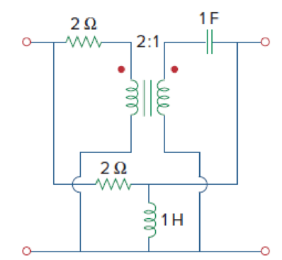
Chapter 19, Problem 69P, The circuit in Fig. 19.116 may be regarded as two two-ports connected in parallel. Obtain the y

Figure 19.116

Expert Solution & Answer
Check Mark
To determine

Find the admittance parameters for the given two-port network in Figure 19.116 in the textbook.

Answer to Problem 69P

The admittance parameters for the given two-port network are [s+1s+2(3s+2)2(s+2)(3s+2)2(s+2)5s2+4s+42s(s+2)]_.

Explanation of Solution

Given Data:

Refer to Figure 19.116 in the textbook for the given two-port network.

Formula used:

Write the expressions for admittance parameters of a two-port network as follows:

I1=y11V1+y12V2        (1)

I2=y21V1+y22V2        (2)

Calculation:

Note that the dimensions are neglected for simple calculations.

Consider upper network as network Na and lower network as Nb.

As the interconnection network is a parallel combination of two networks, it is easier to obtain the required objective in terms of admittance parameters. Find the admittance parameters for upper and lower network and add them to obtain the overall admittance parameters.

The admittance parameters y11 and y21 are obtained when the port-2 of the network is short circuited. The voltage V2 becomes zero when port-2 is short-circuited. Therefore, rewrite the expressions in Equation (1) and (2) by substituting 0 V for V2 as follows:

I1=y11V1+y12(0)=y11V1

y11=I1V1        (3)

I2=y21V1+y22(0)=y21V1

y21=I2V1        (4)

Redraw the upper network by short circuiting the port-2 as shown in Figure 1.

Fundamentals of Electric Circuits, Chapter 19, Problem 69P , additional homework tip  1

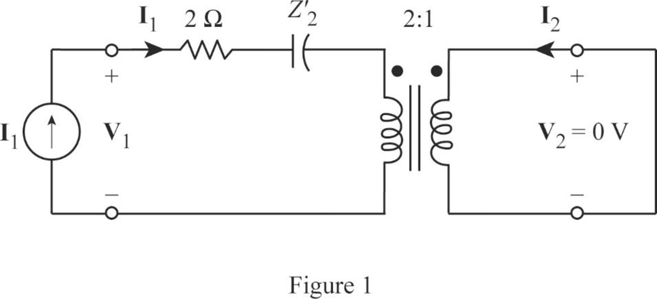
Write the expression for equivalent impedance of secondary winding capacitance when the transformer is referred to the primary winding as follows:

Z2=XCn2        (5)

Here,

XC is the secondary winding reactance, which is 1s and

n is the transformer ratio, which is 12.

Substitute 1s for XC and 12 for n in Equation (5) to find the value of Z2.

Z2=1s(12)2=4s

From Figure 1, write the expression for V1 as follows:

V1=(2+Z2)I1

Substitute 4s for Z2 as follows:

V1=(2+4s)I1

V1=(2s+4s)I1        (6)

Rearrange the expression as follows:

I1V1=s2s+4=s2(s+2)

Substitute s2(s+2) for I1V1 in Equation (3) to obtain the value of y11 for upper network.

y11=s2(s+2)

From Figure 1, write the expression for I2 as follows:

I2=I1n

From Equation (6), substitute (s2s+4)V1 for I1 and 12 for n as follows:

I2=(s2s+4)V112=(2s2s+4)V1=(ss+2)V1

Rearrange the expression as follows:

I2V1=ss+2

Substitute (ss+2) for I2V1 in Equation (4) to obtain the value of y21 for upper network.

y21=ss+2

The admittance parameters y12 and y22 are obtained when the port-1 of the network is short circuited. The current V1 becomes zero when port-1 is short-circuited. Therefore, rewrite the expressions in Equation (1) and (2) by substituting 0 V for V1 as follows:

I1=y11(0)+y12V2=y12V2

y12=I1V2        (7)

I2=y21(0)+y22V2=y22V2

y22=I2V2        (8)

Redraw the given two-port network by short circuiting the port-1 as shown in Figure 2.

Fundamentals of Electric Circuits, Chapter 19, Problem 69P , additional homework tip  2

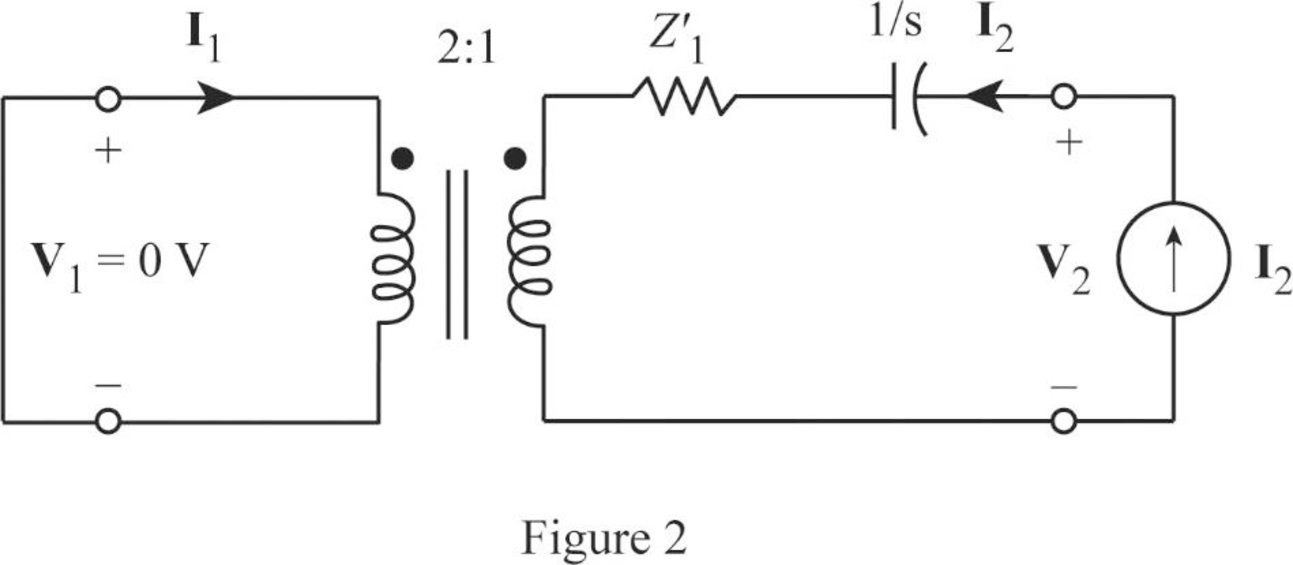
Write the expression for equivalent impedance of primary winding resistance when the transformer is referred to the secondary winding as follows:

Z1=n2R        (9)

Here,

R is the primary winding resistance.

Substitute 2Ω for R and 12 for n in Equation (9) to find the value of Z1.

Z1=(12)2(2Ω)=0.5Ω

From Figure2, write the expression for V2 as follows:

V2=(Z1+1s)I2

Substitute 0.5 for Z1 as follows:

V2=(0.5+1s)I2

V2=(0.5s+1s)I2        (10)

Rearrange the expression as follows:

I2V2=s0.5s+1=s0.5(s+10.5)=2ss+2

Substitute 2ss+2 for I2V2 in Equation (8) to obtain the value of y22 for upper network.

y22=2ss+2

From Figure 1, write the expression for I1 as follows:

I1=nI2

From Equation (10), substitute (s0.5s+1)V2 for I2 and 12 for n as follows:

I1=(12)(s0.5s+1)V2=(ss+2)V2

Rearrange the expression as follows:

I1V2=ss+2

Substitute (ss+2) for I1V2 in Equation (7) to obtain the value of y12 for upper network.

y12=ss+2

From the calculations, write the y-parameters for upper network as follows:

[ya]=[s2(s+2)ss+2ss+22ss+2]

Redraw the lower network by short circuiting the port-2 as shown in Figure 3.

Fundamentals of Electric Circuits, Chapter 19, Problem 69P , additional homework tip  3

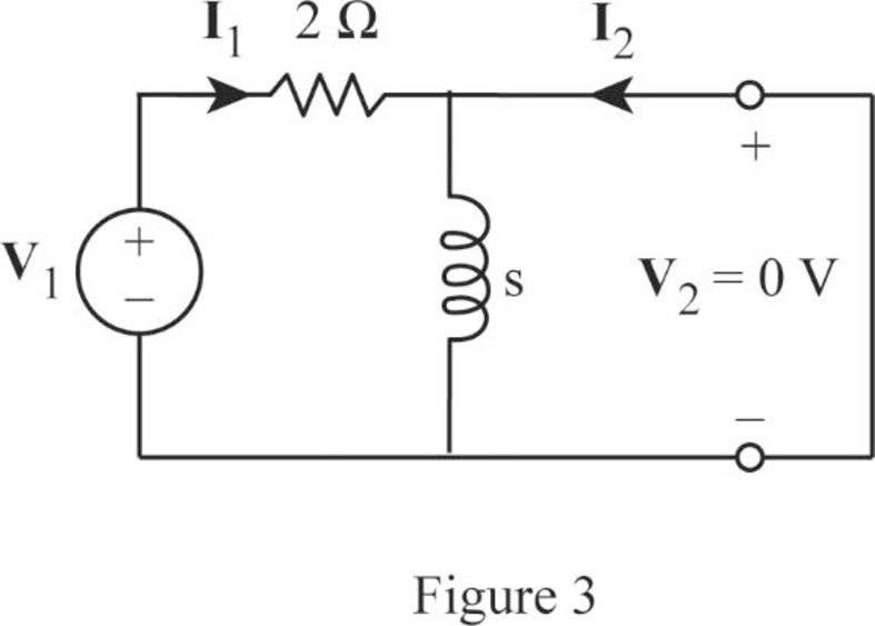
As the current bypasses through the short circuit path, redraw the circuit in Figure 3 as shown in Figure 4.

Fundamentals of Electric Circuits, Chapter 19, Problem 69P , additional homework tip  4

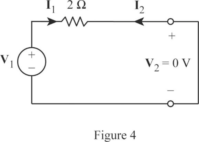
From Figure 4, write the expression for I1 as follows:

I1=V12        (11)

Rearrange the expression as follows:

I1V1=12=0.5

Substitute 0.5 for I1V1 in Equation (3) to obtain the value of y11 for lower network.

y11=0.5

From Figure 1, the expression for current I2 is written as follows:

I2=I1

From Equation (11), substitute V12 for I1 as follows:

I2=V12

Rearrange the expression as follows:

I2V1=12=0.5

Substitute (0.5) for I2V1 in Equation (4) to obtain the value of y21 for lower network.

y21=0.5

Redraw the lower network by short circuiting the port-1 as shown in Figure 5.

Fundamentals of Electric Circuits, Chapter 19, Problem 69P , additional homework tip  5

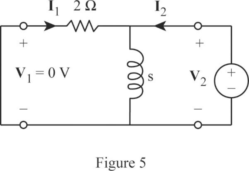
From Figure 5, write the expression for I2 as follows:

I2=V2(2s)=V2(2)(s)2+s

I2=(s+22s)V2        (12)

Rearrange the expression as follows:

I2V2=s+22s

Substitute s+22s for I2V2 in Equation (8) to obtain the value of y22 for lower network.

y22=s+22s

From Figure 5, obtain the current I1 by using current division rule as follows:

I1=I2(ss+2)

From Equation (12), substitute (s+22s)V2 for I2 as follows:

I1=[(s+22s)V2](ss+2)=0.5V2

Rearrange the expression as follows:

I1V2=0.5

Substitute 0.5 for I1V2 in Equation (7) to obtain the value of y12 for lower network.

y12=0.5

From the calculations, write the y-parameters for lower network as follows:

[yb]=[0.50.50.5s+22s]

As the upper and lower networks are connected in parallel, write the expression for overall admittance parameters as follows:

[y]=[ya]+[yb]

Substitute [s2(s+2)ss+2ss+22ss+2] for [ya] and [0.50.50.5s+22s] for [yb] to obtain the required objective.

[y]=[s2(s+2)ss+2ss+22ss+2]+[0.50.50.5s+22s]=[s2(s+2)+0.5ss+2+(0.5)ss+2+(0.5)2ss+2+s+22s]=[s+s+22(s+2)s0.5s1s+2s0.5s1s+2(2s)(2s)+(s+2)(s+2)(s+2)(2s)]=[s+1s+2(1.5s+1)s+2(1.5s+1)s+24s2+s2+4s+42s(s+2)]

Simplify the expression as follows:

[y]=[s+1s+2(3s+2)2(s+2)(3s+2)2(s+2)5s2+4s+42s(s+2)]

Conclusion:

Thus, the admittance parameters for the given two-port network are [s+1s+2(3s+2)2(s+2)(3s+2)2(s+2)5s2+4s+42s(s+2)]_.

Want to see more full solutions like this?

Subscribe now to access step-by-step solutions to millions of textbook problems written by subject matter experts!
Students have asked these similar questions
Find the z parameters for the two-port network
Find the z parameters for the circuit
Derive the expressions for the g parameters as functions of the zparameters.

Chapter 19 Solutions

Fundamentals of Electric Circuits

Ch. 19.6 - Find the z parameters of the op amp circuit in...Ch. 19.7 - Find V2/Vs in the circuit in Fig. 19.43. Figure...Ch. 19.7 - Obtain the y parameters for the network in Fig....Ch. 19.7 - Obtain the ABCD parameter representation of the...Ch. 19.8 - Obtain the h parameters for the network in Fig....Ch. 19.8 - Obtain the z parameters of the circuit in Fig....Ch. 19.9 - For the transistor amplifier of Fig. 19.60, find...Ch. 19.9 - Prob. 18PPCh. 19 - For the single-element two-port network in Fig....Ch. 19 - For the single-element two-port network in Fig....Ch. 19 - For the single-element two-port network in Fig....Ch. 19 - For the single-element two-port network in Fig....Ch. 19 - For the single-element two-port network in Fig....Ch. 19 - For the single-element two-port network in Fig....Ch. 19 - When port 1 of a two-port circuit is...Ch. 19 - A two-port is described by the following...Ch. 19 - If a two-port is reciprocal, which of the...Ch. 19 - Prob. 10RQCh. 19 - Obtain the z parameters for the network in Fig....Ch. 19 - Find the impedance parameter equivalent of the...Ch. 19 - Find the z parameters of the circuit in Fig....Ch. 19 - Using Fig. 19.68, design a problem to help other...Ch. 19 - Obtain the z parameters for the network in Fig....Ch. 19 - Compute the z parameters of the circuit in Fig....Ch. 19 - Calculate the z parameters of the circuit in Fig....Ch. 19 - Find the z parameters of the two-port in Fig....Ch. 19 - The y parameters of a network are:...Ch. 19 - Construct a two-port that realizes each of the...Ch. 19 - Determine a two-port network that is represeted by...Ch. 19 - For the circuit shown in Fig. 19.73, let z=106412...Ch. 19 - Determine the average power delivered to ZL = 5 +...Ch. 19 - For the two-port network shown in Fig. 19.75, show...Ch. 19 - For the two-port circuit in Fig. 19.76,...Ch. 19 - For the circuit in Fig. 19.77, at = 2 rad/s, z11...Ch. 19 - Prob. 17PCh. 19 - Calculate the y parameters for the two-port in...Ch. 19 - Using Fig. 19.80, design a problem to help other...Ch. 19 - Find the y parameters for the circuit in Fig....Ch. 19 - Obtain the admittance parameter equivalent circuit...Ch. 19 - Obtain the y parameters of the two-port network in...Ch. 19 - (a) Find the y parameters of the two-port in Fig....Ch. 19 - Find the resistive circuit that represents these y...Ch. 19 - Prob. 25PCh. 19 - Calculate [y] for tle two-port in Fig. 19.85.Ch. 19 - Find the y parameters for the Circuit in Fig....Ch. 19 - In the circuit of Fig. 19.65, the input port is...Ch. 19 - In the bridge circuit of Fig. 19.87, I1 = 20 A and...Ch. 19 - Find the h parameters for the networks in Fig....Ch. 19 - Determine the hybrid parameters for the network in...Ch. 19 - Using Fig. 19.90, design a problem to help other...Ch. 19 - Obtain the h parameters for the two-port of Fig....Ch. 19 - Obtain the h and g parameters of the two-port in...Ch. 19 - Determine the h parameters for the network in Fig....Ch. 19 - For the two-port in Fig. 19.94. h=16320.01S Find:...Ch. 19 - The input port of the circuit in Fig. 19.79 is...Ch. 19 - The h parameters of the two-port of Fig. 19.95...Ch. 19 - Obtain the g parameters for the wye circuit of...Ch. 19 - Using Fig. 19.97, design a problem to help other...Ch. 19 - For the two-port in Fig. 19.75, show that...Ch. 19 - The h parameters of a two-port device are given by...Ch. 19 - Find the transmission parameters for the...Ch. 19 - Using Fig. 19.99, design a problem to help other...Ch. 19 - Find the ABCD parameters for the circuit in Fig....Ch. 19 - Find the transmission parameters for the circuit...Ch. 19 - Obtain the ABCD parameters for the network in Fig....Ch. 19 - For a two-port, let A = 4, B = 30 , C = 0.1 S, and...Ch. 19 - Using impedances in the s-domain, obtain the...Ch. 19 - Derive the s-domain expression for the t...Ch. 19 - Obtain the t parameters for the network in Fig....Ch. 19 - (a) For the T network in Fig. 19.106, show that...Ch. 19 - Prob. 53PCh. 19 - Show that the transmission parameters of a...Ch. 19 - Prove that the g parameters can be obtained from z...Ch. 19 - For the network of Fig. 19.107, obtain VoVs....Ch. 19 - Given the transmission parameters T=32017 obtain...Ch. 19 - Design a problem to help other students better...Ch. 19 - Given that g=0.06S0.40.22 determine: (a) [z] (b)...Ch. 19 - Design a T network necessary to realize the...Ch. 19 - For the bridge circuit in Fig. 19.108, obtain: (a)...Ch. 19 - Find the z parameters of the op amp circuit in...Ch. 19 - Determine the z parameters of the two-port in Fig....Ch. 19 - Determine the y parameters at = 1,000 rad/s for...Ch. 19 - What is the y parameter presentation of the...Ch. 19 - In the two-port of Fig. 19.113, let y12 = y21 = 0,...Ch. 19 - If three copies of the circuit in Fig. 19.114 are...Ch. 19 - Obtain the h parameters for the network in Fig....Ch. 19 - The circuit in Fig. 19.116 may be regarded as two...Ch. 19 - For the parallel-series connection of the two...Ch. 19 - Determine the z parameters for the network in Fig....Ch. 19 - A series-parallel connection of two two-ports is...Ch. 19 - Three copies of the circuit shown in Fig. 19.70...Ch. 19 - Determine the ABCD parameters of the circuit in...Ch. 19 - For the individual two-ports shown in Fig. 19.121...Ch. 19 - Use PSpice or MultiSim to obtain the z parameters...Ch. 19 - Using PSpice or MultiSim, find the h parameters of...Ch. 19 - Obtain the h parameters at = 4 rad/s for the...Ch. 19 - Use PSpice or MultiSim to determine the z...Ch. 19 - Use PSpice or MultiSim to find the z parameters of...Ch. 19 - Repeat Prob. 19.26 using PSpice or MultiSim....Ch. 19 - Use PSpice or MultiSim to rework Prob. 19.31....Ch. 19 - Rework Prob. 19.47 using PSpice or MultiSim....Ch. 19 - Using PSpice or MultiSim, find the transmission...Ch. 19 - At =1rad/s, find the transmission parameters of...Ch. 19 - Obtain the g parameters for the network in Fig....Ch. 19 - For the circuit shown in Fig. 19.129, use PSpice...Ch. 19 - Using the y parameters, derive formulas for Zin,...Ch. 19 - A transistor has the following parameters in a...Ch. 19 - A transistor with hfe=120,hie=2khre=104,hoe=20S is...Ch. 19 - For the transistor network of Fig. 19.130,...Ch. 19 - Prob. 92PCh. 19 - Prob. 93PCh. 19 - A transistor in its common-emitter mode is...Ch. 19 - Prob. 95PCh. 19 - Prob. 96PCh. 19 - Synthesize the transfer function...Ch. 19 - A two-stage amplifier in Fig. 19.134 contains two...Ch. 19 - Assume that the two circuits in Fig. 19.135 are...
Knowledge Booster
Background pattern image
Electrical Engineering
Learn more about
Need a deep-dive on the concept behind this application? Look no further. Learn more about this topic, electrical-engineering and related others by exploring similar questions and additional content below.
Similar questions
SEE MORE QUESTIONS
Recommended textbooks for you
Text book image
Introductory Circuit Analysis (13th Edition)
Electrical Engineering
ISBN:9780133923605
Author:Robert L. Boylestad
Publisher:PEARSON
Text book image
Delmar's Standard Textbook Of Electricity
Electrical Engineering
ISBN:9781337900348
Author:Stephen L. Herman
Publisher:Cengage Learning
Text book image
Programmable Logic Controllers
Electrical Engineering
ISBN:9780073373843
Author:Frank D. Petruzella
Publisher:McGraw-Hill Education
Text book image
Fundamentals of Electric Circuits
Electrical Engineering
ISBN:9780078028229
Author:Charles K Alexander, Matthew Sadiku
Publisher:McGraw-Hill Education
Text book image
Electric Circuits. (11th Edition)
Electrical Engineering
ISBN:9780134746968
Author:James W. Nilsson, Susan Riedel
Publisher:PEARSON
Text book image
Engineering Electromagnetics
Electrical Engineering
ISBN:9780078028151
Author:Hayt, William H. (william Hart), Jr, BUCK, John A.
Publisher:Mcgraw-hill Education,
Z Parameters - Impedance Parameters; Author: Electrical Engineering Authority;https://www.youtube.com/watch?v=qoD4AoNmySA;License: Standard Youtube License