
Electric Motor Control
10th Edition
ISBN: 9781133702818
Author: Herman
Publisher: CENGAGE L
expand_more
expand_more
format_list_bulleted
Concept explainers
Videos
Textbook Question
Chapter 19, Problem 6SQ
Refer to the chart in Figure 19–5. At what position must the HOA switch be set in order for contacts 7 and 8 to be closed?
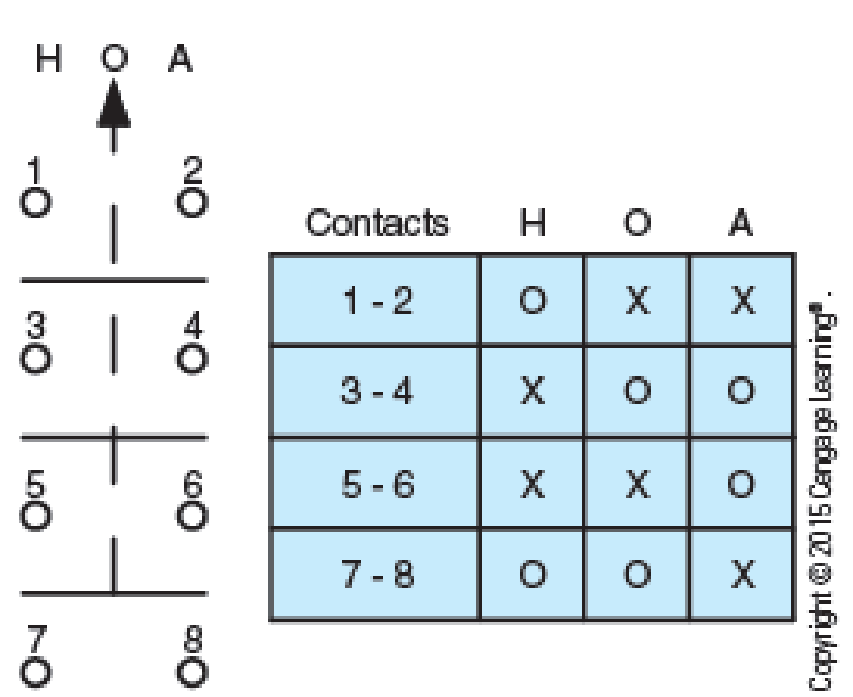
Fig. 19–5 Selector switch with multiple double-break contacts.
Expert Solution & Answer

Trending nowThis is a popular solution!

Students have asked these similar questions
19.b. In a DC system, the bonding jumper between the negative of the supply and ground is normally madeat the source or at theA. end of the DC line.B. first disconnecting means.C. first device on the supply.D. entrance to the building.
Devise ladder programs for systems that will carry out the following Internal Relay tasks: Start a machine if switch B is closed within 0.5 s of switch A being closed; otherwise the machine is not switched on.
Describe the effects on a level transmitter of the following abnormalities in a wet leg cinfiguration:
a) a leak in the high-pressure sensing lines
b) a leak in the low-pressure sensing line
c) a completed block low pressure sensing line
Strictly no plagiarism please
Knowledge Booster


Learn more about
Need a deep-dive on the concept behind this application? Look no further. Learn more about this topic, electrical-engineering and related others by exploring similar questions and additional content below.Similar questions
- Refer to the chart in Figure 195. When the switch is set in the off position, are contacts 5 and 6 open or closed? Fig. 195 Selector switch with multiple double-break contacts.arrow_forwardQ1. Construct a delay formula for both types of switching (circuit and datagram) if the packet/message has to pass through 4 switches from source to destination. Show the delay diagram for both types. Write the delay formula for both types.arrow_forwardDraw a block diagram of generalized communication system. Write the functions of each of the following: (a) Transmitter (b) Channel (c) Receiverarrow_forward
- do it correctlyarrow_forwardDon't use AI.....arrow_forwardGive the reason for the following statements: 1) Using a Venturi flow sensor makes the measurement error due to pressure loading is much lower.?2) For the measurement systems, the signal conditioning element is an important one.?3) Null-type AC Bridge can not be used for measuring the inductive impedance.?arrow_forward
- in the conduit diagram shown in figure 17-3 determine how many wires are in each conduit between each piece of equipment.identify each wire terminal connection and quantity of wires above the disconnect switch, as shown in the example? based on electric motor control 1th edition by sthephen l. hermanarrow_forwardDefine constellation diagram and its role in analog transmission.arrow_forwardFrom the elementary drawing in Figure 2110, determine the number and terminal identification of the wiring in each conduit in the conduit layout. Indicate your solutions in the same manner as the example given below the disconnect switch. FIG. 2110arrow_forward
arrow_back_ios
SEE MORE QUESTIONS
arrow_forward_ios
Recommended textbooks for you

 Electricity for Refrigeration, Heating, and Air C...Mechanical EngineeringISBN:9781337399128Author:Russell E. SmithPublisher:Cengage Learning
Electricity for Refrigeration, Heating, and Air C...
Mechanical Engineering
ISBN:9781337399128
Author:Russell E. Smith
Publisher:Cengage Learning
Latches and Flip-Flops 1 - The SR Latch; Author: Computer Science;https://www.youtube.com/watch?v=-aQH0ybMd3U;License: Standard Youtube License