
Calculate the voltage gain, current gain, input impedance, and output impedance for the amplifier shown in Figure 19.131 in the textbook.
Answer to Problem 92P
The voltage gain, current gain, input impedance, and output impedance for the amplifier are
Explanation of Solution
Given Data:
Refer to Figure 19.131 in the textbook for the amplifier circuit.
From the given amplifier circuit, the internal resistance
Formula used:
Refer to Equation 19.73 in the textbook and write the expression for voltage gain of a amplifier in terms of hybrid parameters as follows:
Here,
Write the expression for current gain of the amplifier as follows:
Here,
Write the expression for input impedance of the amplifier as follows:
Calculation:
Redraw the given circuit as shown in Figure 1.
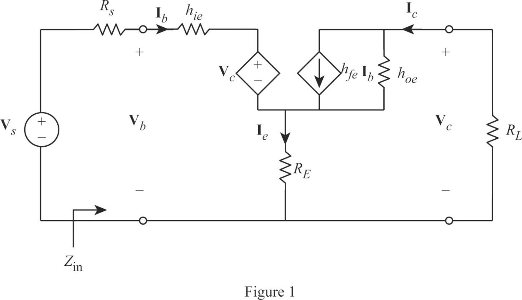
From Figure 1, write the expression for emitter current as follows:
Write the expression for base voltage from the circuit in Figure 1 as follows:
Write the expression for collector current as follows:
Write the expression for collector voltage as follows:
From Equation (7), substitute
Rearrange the expression as follows:
From Equation (2), substitute
Substitute 100 for
From Equation (6), substitute
Rearrange the expression as follows:
Rearrange the expression in Equation (5) as follows:
From Equations (7) and (9), substitute
Rearrange the expression as follows:
Substitute 100 for
Simplify the expression as follows:
From Equation (1), substitute
From Equation (9), substitute
Rearrange the expression as follows:
Substitute 100 for
From Equation (3), substitute
Consider output voltage
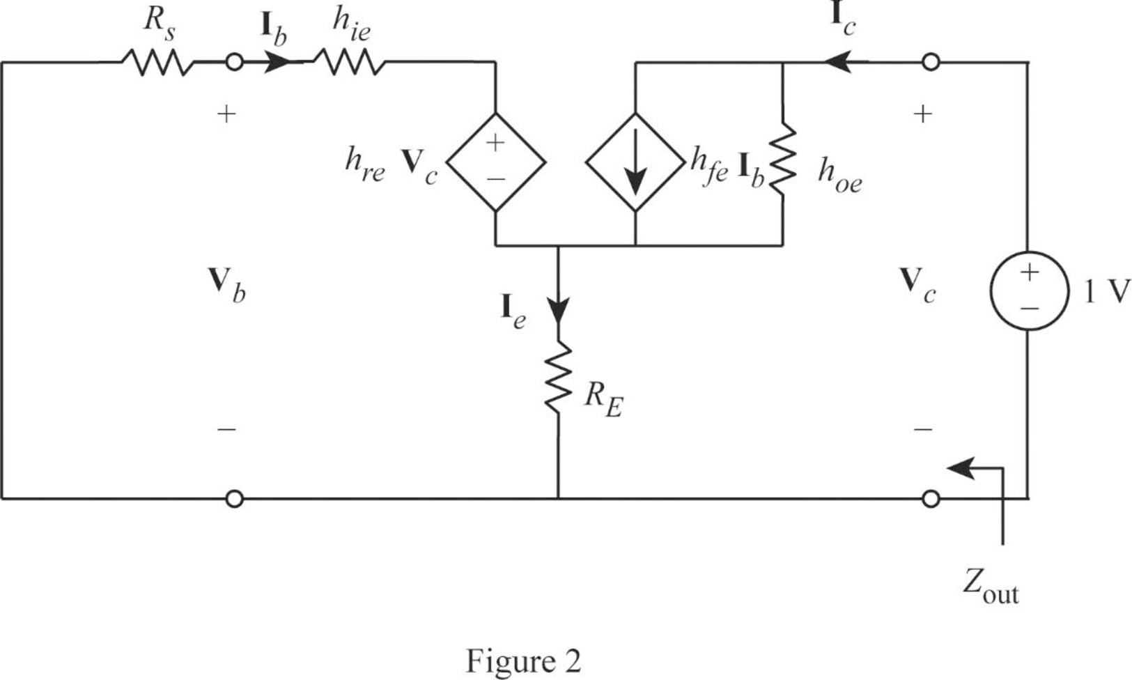
Apply KVL to the input loop for the circuit in Figure 2 as follows:
Substitute 1 for
Apply KCL at the output node for the circuit in Figure 2 as follows:
Substitute 1 for
Rearrange the expression as follows:
From Equation (12), substitute
Substitute 100 for
Write the expression for output impedance of the amplifier as follows:
Substitute 1 for
Conclusion:
Thus, the voltage gain, current gain, input impedance, and output impedance for the amplifier are
Want to see more full solutions like this?
Chapter 19 Solutions
Fundamentals of Electric Circuits

- .Calculate the a parameters for the two-port impedances (complex Values)arrow_forwardConsider the causal discrete-time LTI systems characterized by the following difference equations: 1. y[n] = 0.3 x[n] + 1.5 x[n-1] – 0.1y[n-1] + 0.5 y[n-2] • Determine whether each system is FIR or IIRarrow_forwardFind the z parameters for the circuitarrow_forward
- Determine (draw) a two-port network that is represented by the following z parameters.arrow_forwardConsider the input signal to an LTI system as x(t)= etu(−t).If the output to the system is measured as y(t)=e-tsint u(t) + e-tu(t) + 2etu(-t) a) sketch the pole-zero plot b)Is the system causal and stable?Just if your answersarrow_forwardThe relationship between input and output for an LTI system is defined by the following difference equation. Calculate the system output y[n] for system input x[n] = u[n] using z transformations (y[-1]=1 , y[-2] =2).arrow_forward
- Be able to calculate any set of two-port parameters The following measurements were made on a two-port resistive circuit: With port 1 open, V2=15 V, V1=10 V, and I2=30 A; with port 1short-circuited, V2=10 V, I2=4 A, and I1=−5 A. Calculate the zparameters.arrow_forwardThe sampling rate of a system is 50,000 samples per second. Calculate the maximum frequency of the signal that can be obtained to reproduce it.arrow_forwardBe able to calculate any set of two-port parameters The following measurements were made on a resistive two-portnetwork that is symmetric and reciprocal: With port 2 open, V1=95 Vand I1=5 A; with a short circuit across port 2, V1=11.52 V and I2=−2.72 A. Calculate the z parameters of the two-port network.arrow_forward
 Introductory Circuit Analysis (13th Edition)Electrical EngineeringISBN:9780133923605Author:Robert L. BoylestadPublisher:PEARSON
 Delmar's Standard Textbook Of ElectricityElectrical EngineeringISBN:9781337900348Author:Stephen L. HermanPublisher:Cengage Learning
 Programmable Logic ControllersElectrical EngineeringISBN:9780073373843Author:Frank D. PetruzellaPublisher:McGraw-Hill Education
 Fundamentals of Electric CircuitsElectrical EngineeringISBN:9780078028229Author:Charles K Alexander, Matthew SadikuPublisher:McGraw-Hill Education
 Electric Circuits. (11th Edition)Electrical EngineeringISBN:9780134746968Author:James W. Nilsson, Susan RiedelPublisher:PEARSON
 Engineering ElectromagneticsElectrical EngineeringISBN:9780078028151Author:Hayt, William H. (william Hart), Jr, BUCK, John A.Publisher:Mcgraw-hill Education,