Fundamentals of Electric Circuits
6th Edition
ISBN: 9780078028229
Author: Charles K Alexander, Matthew Sadiku
Publisher: McGraw-Hill Education
bartleby

Concept explainers

bartleby

Videos

Textbook Question
Book Icon
Chapter 19, Problem 98P

A two-stage amplifier in Fig. 19.134 contains two identical stages with

[ h ] = 2  kΩ 0.004 200 500   μ S

If ZL = 20 kΩ, find the required value of Vs to produce Vo = 16 V.

Chapter 19, Problem 98P, A two-stage amplifier in Fig. 19.134 contains two identical stages with [h]=2k0.004200500S If ZL =

Figure 19.134

Expert Solution & Answer
Check Mark
To determine

Calculate the required source voltage for the given two-stage amplifier.

Answer to Problem 98P

The required source voltage for the given two-stage amplifier is 464.224μV_.

Explanation of Solution

Given Data:

The h parameters of each stage of the amplifier are given as follows:

[h]=[2kΩ0.004200500μS]

The load impedance and output voltage of the given two-stage amplifier are given as follows:

ZL=20kΩVo=16V

Refer to Figure 19.134 in the textbook for the given two-stage amplifier circuit.

Formula used:

Refer to TABLE 19.1 in the textbook, write the expression for transmission parameters in terms of h parameters as follows:

[T]=[Δhh21h11h21h22h211h21]        (1)

Write the expression for Δh as follows:

Δh=h11h22h12h21        (2)

Write the expression for ΔT as follows:

ΔT=ADBC        (3)

From TABLE 19.1 in the textbook, write the expression for impedance parameters in terms of transmission parameters as follows:

[z]=[ACΔTC1CDC]        (4)

Calculation:

From the given circuit, the two-stage amplifier is the cascade connection of two identical transistors. Obtain the transmission parameters for two-stage amplifier and then convert into impedance parameters for simple analysis.

Find the transmission parameters for one stage of the two-stage amplifier as follows:

Substitute 2kΩ for h11, 0.004 for h12, 200 for h21, and 500μS for h22 in Equation (2) to obtain the value of Δh.

Δh=(2kΩ)(500μS)(0.004)(200)=(2×10³Ω)(500×106S)0.8=10.8=0.2

Substitute 2kΩ for h11, 0.004 for h12, 200 for h21, 500μS for h22, and 0.2 for Δh in Equation (1) to obtain the transmission parameters.

[T1]=[0.22002kΩ200500μS2001200]=[1×1032×103Ω200500×106S2001200]=[0.00110Ω2.5×10⁶S0.005]

As both the stages are identical, the transmission parameters of second stage of the amplifier are equal to the first stage.

[T2]=[T1]=[0.00110Ω2.5×10⁶S0.005]

As the two identical stages are connected in cascade to form a two-stage amplifier, write the expression for overall transmission parameters for the amplifier as follows:

[T]=[T1][T2]

Substitute [0.00110Ω2.5×10⁶S0.005] for [T1] and [0.00110Ω2.5×10⁶S0.005] for [T2] as follows:

[T]=[0.00110Ω2.5×10⁶S0.005][0.00110Ω2.5×10⁶S0.005]=[(0.001)(0.001)+(10Ω)(2.5×10⁶S)(0.001)(10Ω)+(10Ω)(0.005)(2.5×10⁶S)(0.001)+(0.005)(2.5×10⁶S)(2.5×10⁶S)(10Ω)+(0.005)(0.005)]=[2.6×1050.06Ω1.5×10⁸S5×105]

From the obtained transmission parameters of the two-stage amplifier, write the transmission parameters as follows:

A=2.6×10⁵B=0.06ΩC=1.5×10⁸SD=5×10⁵

Convert the obtained transmission parameters into impedance parameters as follows:

Substitute 2.6×10⁵ for A, 0.06Ω for B, 1.5×10⁸S for C, and 5×10⁵ for D in Equation (3) to obtain the value of ΔT.

ΔT=(2.6×10⁵)(5×10⁵)(0.06Ω)(1.5×10⁸S)=(13×1010)(0.09×10⁸)=0.04×10⁸

Substitute 2.6×10⁵ for A, 0.06Ω for B, 1.5×10⁸S for C, 5×10⁵ for D, and (0.04×10⁸) for ΔT in Equation (4) to obtain the impedance parameters for given network.

[z]=[2.6×1051.5×108S0.04×1081.5×108S11.5×108S5×1051.5×108S]=[1733.3Ω0.0267Ω0.6667×10⁸Ω3333.3Ω]

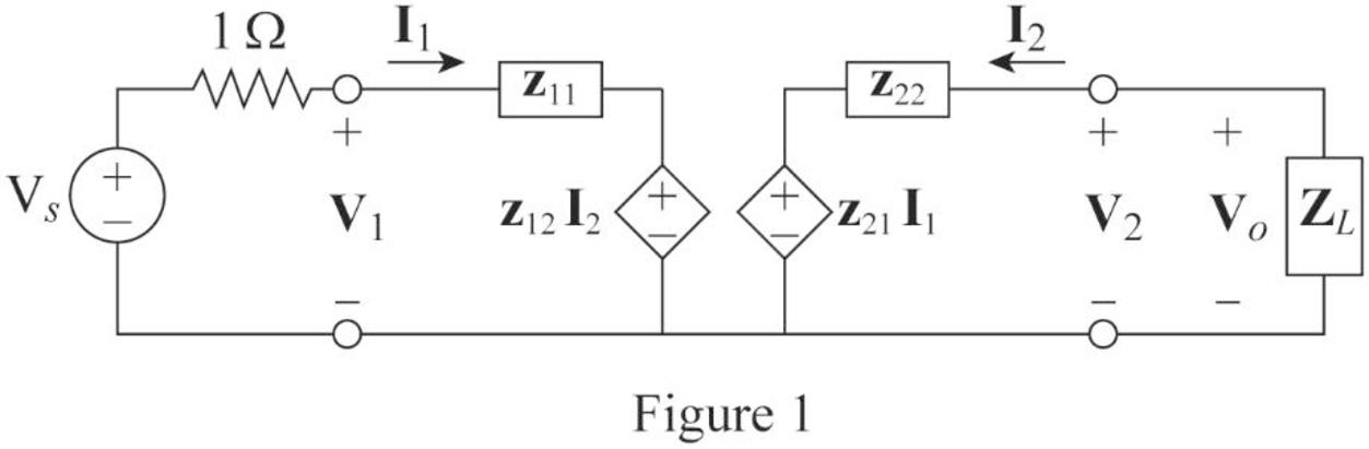
Refer to Figure 19.5 (b) in the textbook for general equivalent circuit of impedance parameters and draw the circuit for given amplifier as shown in Figure 1.

Fundamentals of Electric Circuits, Chapter 19, Problem 98P

From the circuit in Figure 1, apply KVL to the input loop as follows:

Vs+(1Ω+z11)I1+z12I2=0

Simplify the expression as follows:

Vs=(1Ω+z11)I1+z12I2        (5)

From the circuit in Figure 1, apply KVL to the output loop as follows:

Vo+z22I2+z21I1=0

Simplify the expression as follows:

Vo=z22I2+z21I1        (6)

From Figure 1, write the expression for Vo as follows:

Vo=I2ZL

Rearrange the expression as follows:

I2=VoZL        (7)

Substitute (VoZL) for I2 in Equation (6) as follows:

Vo=z22(VoZL)+z21I1z21I1=Vo+z22ZLVo

I1=(1z21+z22z21ZL)Vo        (8)

From Equations (7) and (8), substitute (VoZL) for I2 and (1z21+z22z21ZL)Vo for I1 in Equation (5) as follows:

Vs=(1Ω+z11)(1z21+z22z21ZL)Vo+z12(VoZL)=[(1Ω+z11)(1z21+z22z21ZL)z12ZL]Vo

Substitute 1733.3Ω for z11, 0.0267Ω for z12, (0.6667×10⁸)Ω for z21, 3333.3Ω for z22, 20kΩ for ZL, and 16 V for Vo to obtain the required source voltage to the amplifier.

Vs=((1Ω+1733.3Ω){1(0.6667×10⁸)Ω+3333.3Ω[(0.6667×10⁸)Ω](20kΩ)}0.0267Ω20kΩ)(16V)=((1734.3Ω){(20000Ω)+3333.3Ω[(0.6667×10⁸)Ω](20000Ω)}0.0267Ω20000Ω)(16V)=[(3.0349×10⁵)(0.1335×10⁵)](16V)=(2.9014×10⁵)(16V)

Simplify the expression as follows:

Vs=464.224×10⁶V=464.224μV

Conclusion:

Thus, the required source voltage for the given two-stage amplifier is 464.224μV_.

Want to see more full solutions like this?

Subscribe now to access step-by-step solutions to millions of textbook problems written by subject matter experts!
Students have asked these similar questions
Find the z parameters for the circuit
Be able to calculate any set of two-port parameters Find the y parameters for the circuit
Find the z parameters for the two-port network

Chapter 19 Solutions

Fundamentals of Electric Circuits

Ch. 19.6 - Find the z parameters of the op amp circuit in...Ch. 19.7 - Find V2/Vs in the circuit in Fig. 19.43. Figure...Ch. 19.7 - Obtain the y parameters for the network in Fig....Ch. 19.7 - Obtain the ABCD parameter representation of the...Ch. 19.8 - Obtain the h parameters for the network in Fig....Ch. 19.8 - Obtain the z parameters of the circuit in Fig....Ch. 19.9 - For the transistor amplifier of Fig. 19.60, find...Ch. 19.9 - Prob. 18PPCh. 19 - For the single-element two-port network in Fig....Ch. 19 - For the single-element two-port network in Fig....Ch. 19 - For the single-element two-port network in Fig....Ch. 19 - For the single-element two-port network in Fig....Ch. 19 - For the single-element two-port network in Fig....Ch. 19 - For the single-element two-port network in Fig....Ch. 19 - When port 1 of a two-port circuit is...Ch. 19 - A two-port is described by the following...Ch. 19 - If a two-port is reciprocal, which of the...Ch. 19 - Prob. 10RQCh. 19 - Obtain the z parameters for the network in Fig....Ch. 19 - Find the impedance parameter equivalent of the...Ch. 19 - Find the z parameters of the circuit in Fig....Ch. 19 - Using Fig. 19.68, design a problem to help other...Ch. 19 - Obtain the z parameters for the network in Fig....Ch. 19 - Compute the z parameters of the circuit in Fig....Ch. 19 - Calculate the z parameters of the circuit in Fig....Ch. 19 - Find the z parameters of the two-port in Fig....Ch. 19 - The y parameters of a network are:...Ch. 19 - Construct a two-port that realizes each of the...Ch. 19 - Determine a two-port network that is represeted by...Ch. 19 - For the circuit shown in Fig. 19.73, let z=106412...Ch. 19 - Determine the average power delivered to ZL = 5 +...Ch. 19 - For the two-port network shown in Fig. 19.75, show...Ch. 19 - For the two-port circuit in Fig. 19.76,...Ch. 19 - For the circuit in Fig. 19.77, at = 2 rad/s, z11...Ch. 19 - Prob. 17PCh. 19 - Calculate the y parameters for the two-port in...Ch. 19 - Using Fig. 19.80, design a problem to help other...Ch. 19 - Find the y parameters for the circuit in Fig....Ch. 19 - Obtain the admittance parameter equivalent circuit...Ch. 19 - Obtain the y parameters of the two-port network in...Ch. 19 - (a) Find the y parameters of the two-port in Fig....Ch. 19 - Find the resistive circuit that represents these y...Ch. 19 - Prob. 25PCh. 19 - Calculate [y] for tle two-port in Fig. 19.85.Ch. 19 - Find the y parameters for the Circuit in Fig....Ch. 19 - In the circuit of Fig. 19.65, the input port is...Ch. 19 - In the bridge circuit of Fig. 19.87, I1 = 20 A and...Ch. 19 - Find the h parameters for the networks in Fig....Ch. 19 - Determine the hybrid parameters for the network in...Ch. 19 - Using Fig. 19.90, design a problem to help other...Ch. 19 - Obtain the h parameters for the two-port of Fig....Ch. 19 - Obtain the h and g parameters of the two-port in...Ch. 19 - Determine the h parameters for the network in Fig....Ch. 19 - For the two-port in Fig. 19.94. h=16320.01S Find:...Ch. 19 - The input port of the circuit in Fig. 19.79 is...Ch. 19 - The h parameters of the two-port of Fig. 19.95...Ch. 19 - Obtain the g parameters for the wye circuit of...Ch. 19 - Using Fig. 19.97, design a problem to help other...Ch. 19 - For the two-port in Fig. 19.75, show that...Ch. 19 - The h parameters of a two-port device are given by...Ch. 19 - Find the transmission parameters for the...Ch. 19 - Using Fig. 19.99, design a problem to help other...Ch. 19 - Find the ABCD parameters for the circuit in Fig....Ch. 19 - Find the transmission parameters for the circuit...Ch. 19 - Obtain the ABCD parameters for the network in Fig....Ch. 19 - For a two-port, let A = 4, B = 30 , C = 0.1 S, and...Ch. 19 - Using impedances in the s-domain, obtain the...Ch. 19 - Derive the s-domain expression for the t...Ch. 19 - Obtain the t parameters for the network in Fig....Ch. 19 - (a) For the T network in Fig. 19.106, show that...Ch. 19 - Prob. 53PCh. 19 - Show that the transmission parameters of a...Ch. 19 - Prove that the g parameters can be obtained from z...Ch. 19 - For the network of Fig. 19.107, obtain VoVs....Ch. 19 - Given the transmission parameters T=32017 obtain...Ch. 19 - Design a problem to help other students better...Ch. 19 - Given that g=0.06S0.40.22 determine: (a) [z] (b)...Ch. 19 - Design a T network necessary to realize the...Ch. 19 - For the bridge circuit in Fig. 19.108, obtain: (a)...Ch. 19 - Find the z parameters of the op amp circuit in...Ch. 19 - Determine the z parameters of the two-port in Fig....Ch. 19 - Determine the y parameters at = 1,000 rad/s for...Ch. 19 - What is the y parameter presentation of the...Ch. 19 - In the two-port of Fig. 19.113, let y12 = y21 = 0,...Ch. 19 - If three copies of the circuit in Fig. 19.114 are...Ch. 19 - Obtain the h parameters for the network in Fig....Ch. 19 - The circuit in Fig. 19.116 may be regarded as two...Ch. 19 - For the parallel-series connection of the two...Ch. 19 - Determine the z parameters for the network in Fig....Ch. 19 - A series-parallel connection of two two-ports is...Ch. 19 - Three copies of the circuit shown in Fig. 19.70...Ch. 19 - Determine the ABCD parameters of the circuit in...Ch. 19 - For the individual two-ports shown in Fig. 19.121...Ch. 19 - Use PSpice or MultiSim to obtain the z parameters...Ch. 19 - Using PSpice or MultiSim, find the h parameters of...Ch. 19 - Obtain the h parameters at = 4 rad/s for the...Ch. 19 - Use PSpice or MultiSim to determine the z...Ch. 19 - Use PSpice or MultiSim to find the z parameters of...Ch. 19 - Repeat Prob. 19.26 using PSpice or MultiSim....Ch. 19 - Use PSpice or MultiSim to rework Prob. 19.31....Ch. 19 - Rework Prob. 19.47 using PSpice or MultiSim....Ch. 19 - Using PSpice or MultiSim, find the transmission...Ch. 19 - At =1rad/s, find the transmission parameters of...Ch. 19 - Obtain the g parameters for the network in Fig....Ch. 19 - For the circuit shown in Fig. 19.129, use PSpice...Ch. 19 - Using the y parameters, derive formulas for Zin,...Ch. 19 - A transistor has the following parameters in a...Ch. 19 - A transistor with hfe=120,hie=2khre=104,hoe=20S is...Ch. 19 - For the transistor network of Fig. 19.130,...Ch. 19 - Prob. 92PCh. 19 - Prob. 93PCh. 19 - A transistor in its common-emitter mode is...Ch. 19 - Prob. 95PCh. 19 - Prob. 96PCh. 19 - Synthesize the transfer function...Ch. 19 - A two-stage amplifier in Fig. 19.134 contains two...Ch. 19 - Assume that the two circuits in Fig. 19.135 are...
Knowledge Booster
Background pattern image
Electrical Engineering
Learn more about
Need a deep-dive on the concept behind this application? Look no further. Learn more about this topic, electrical-engineering and related others by exploring similar questions and additional content below.
Similar questions
SEE MORE QUESTIONS
Recommended textbooks for you
Text book image
Introductory Circuit Analysis (13th Edition)
Electrical Engineering
ISBN:9780133923605
Author:Robert L. Boylestad
Publisher:PEARSON
Text book image
Delmar's Standard Textbook Of Electricity
Electrical Engineering
ISBN:9781337900348
Author:Stephen L. Herman
Publisher:Cengage Learning
Text book image
Programmable Logic Controllers
Electrical Engineering
ISBN:9780073373843
Author:Frank D. Petruzella
Publisher:McGraw-Hill Education
Text book image
Fundamentals of Electric Circuits
Electrical Engineering
ISBN:9780078028229
Author:Charles K Alexander, Matthew Sadiku
Publisher:McGraw-Hill Education
Text book image
Electric Circuits. (11th Edition)
Electrical Engineering
ISBN:9780134746968
Author:James W. Nilsson, Susan Riedel
Publisher:PEARSON
Text book image
Engineering Electromagnetics
Electrical Engineering
ISBN:9780078028151
Author:Hayt, William H. (william Hart), Jr, BUCK, John A.
Publisher:Mcgraw-hill Education,
Z Parameters - Impedance Parameters; Author: Electrical Engineering Authority;https://www.youtube.com/watch?v=qoD4AoNmySA;License: Standard Youtube License