
Concept explainers
Videos
The aluminum test specimen shown is subjected to two equal and opposite centric axial forces of magnitude P. (a) Knowing that E = 70 GPa and σall = 200 MPa, determine the maximum allowable value of P and the corresponding total elongation of the specimen, (b) Solve part a, assuming that the specimen has been replaced by an aluminum bar of the same length and a uniform 60 × 15-mm rectangular cross section.
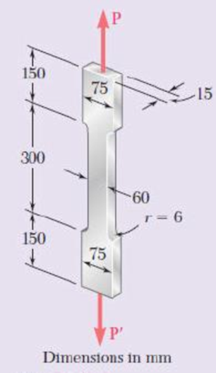
Fig. P2.134
(a)
Find the maximum allowable load value P and corresponding total elongation length of the specimen.
Answer to Problem 134RP
The maximum allowable load value P is
The total elongation length of the specimen is
Explanation of Solution
Given information:
The modulus of elasticity (E) is
The allowable stress
The width (D) of the specimen is
The width (d) of the fillet is
The radius of the fillet is
The uniform rectangular cross section is
Calculation:
Determine the area (A) of the cross section as follows:
Here, b is the width of the specimen and t is thickness of specimen.
Substitute
Test specimen:
Calculate the ratio of
Substitute
Calculate the ratio of
Substitute
Refer to Figure 2.52b (flat bars with fillets), “Stress concentration factors for flat bars under axial loading” in the textbook.
Get the stress concentration factor (K) using the ratio of
Get the value of K is 1.95 for the corresponding value of
Calculate the maximum allowable load using the expression as follows:
Here, K is stress concentration factor and
Substitute
Thus, the maximum allowable value P is
Determine the wide area
Substitute
Determine the total elongation of the specimen using the relation:
Substitute
Thus, the total elongation of the specimen is
(b)
Find the maximum allowable load value P of an aluminium bar and total elongation length of the aluminum bar.
Answer to Problem 134RP
The maximum allowable load value P is
The total elongation length of the aluminum bar is
Explanation of Solution
Calculation:
Calculate the maximum allowable load of uniform bar as follows:
Substitute
Thus, the maximum allowable value P is
Calculate the total elongation of uniform bar as follows:
Substitute
Thus, the total elongation of the uniform bar is
Want to see more full solutions like this?
Chapter 2 Solutions
Mechanics of Materials, 7th Edition


- A rectangular aluminum block is 100 mm long in the x direction, 75 mm wide in the y direction and 50 mm thick in the z direction. It is subjected to a triaxial loading consisting of a uniformly distributed tensile forces of 200 kN in the x direction and uniformly distributed compressive forces of 160 kN in the y direction and 220 kN in the z direction. If n = 1/3 and E = 70 GPa, determine the resultant deformation in the x, y and z direction. Determine also a single distributed loading in the x direction that would produce the same z deformation as the original loading.arrow_forwardA 5.3-m-long steel rod must not stretch more than 2.71 mm and the normal stress must not exceed 181 MPa when the rod is subjected to a 9.99-kNaxial load. Knowing that E = 199.3 GPa, determine the required radius of the rod in mm. Express your answer in four decimal places.arrow_forwardTwo steel plates are to be held together by means of 16-mm-diameter high-strength steel bolts fitting snugly inside cylindrical brass spacers. Knowing that the average normal stress must not exceed 205 MPa in the bolts and 132 MPa in the spacers, determine the outer diameter of the spacers that yields the most economical and safe design. The outer diameter of the spacers that yields the most economical and safe design is mm.arrow_forward
- The 1021-kg uniform bar AB is suspended from two cables AC and BD each with cross-sectional area 472 mm2. Find the magnitude of P (in N) that can be safely applied to the bar if the stresses in AC and BD are limited to 110 MPa and 51 MPa, respectively. Express your answer in two decimal places.arrow_forwardA 5-kN tensile load will be applied to a 50-m length of steel wire with E = 200 GPa. Determine the smallest diameter wire that can be used, knowing that the normal stress must not exceed 150 MPa and that the increase in length of the wire must not exceed 25 mm.arrow_forwardTwo cylindrical rods, one of steel and the other of brass, are joined at C and restrained by rigid supports at A and E. The steel rod has a length of 300 mm while the brass rod has a length of 200 mm. The diameters of the rods are shown in the figure below. A force of 60 kN is applied at point B of the steel segment. For the loading shown and knowing that modulus of elasticity values for steel and brass are respectively Es = 200 GPa and Eb = 105 GPa, determine a.) The reactions at A and E: RA and RE. b.) The deflection of point C from its original location. how to doarrow_forward
- A rectangular steel block is 4 inches long in the x direction, 2 inches long in the y direction, and 3 inches long in the z direction. The block is subjected to a triaxial loading of three resultant forces as follows: 72 kips compression in the x direction, 60 kips tension in the y direction, and 56 kips tension in the z direction. If ν = 1/3 and E = 29 x 106 psi, ( a ) determine the single resultant load in the z direction that would produce the same deformation in x direction as the original loadings. ( b ) determine the single resultant load in the y direction that would produce the same deformation in x direction as the original loadings.arrow_forwardThe rod ABC is made of aluminum for which E = 70 GPa. Force P = 42 kN and Q = 6 kN. Rod AB is 20 mm in diameter and 0.40 m long while Rod BC is 60 mm in diameter and 0.50 m long. Determine the deformation in mm of (a) rod AB and (b) rod ABC.arrow_forwardIn many situations physical constraints prevent strain from occurring in a given direction. For example, εz= 0 in the case shown, where longitudinal movement of the long prism is prevented at every point. Plane sections perpendicular to the longitudinal axis remain plane and the same distance apart. Show that for this situation, which is known as plane strain, we can express σz, εx, and εy as followsarrow_forward
- A fabric used in air-inflated structures is subjected to a biaxial loading that results in normal stresses ox = 18 ksi and oz = 24 ksi.Knowing that the properties of the fabric can be approximated as E = 12.6 x 10 psi and v = 0.34, determine the change in length of (a) side AB, (b) side BC, (c) diagonal AC.arrow_forwardA rod hanging from a support whose unit mass is 3900 kg/ m3 has a cross-sectional area of 400 mm2 and 250 meters long. If the load of 18 kN is applied at its free end and E = 200 x 103 MPa, determine, a) Elongation due to its ownweight in mm, b) Elongation due to the applied load in mm and c) Total elongation in mm.arrow_forwardA 13-mm-diameter steel (E = 193 GPa) rod (2) is connected to a 27-mm-wide by 10-mm-thick rectangular aluminum (E = 72 GPa) bar (1), as shown. Assume L1 = 0.74 m and L2 = 1.38 m. Determine the force P (in kN rounded to the nearest tenths) required to stretch the assembly 8.1 mm.arrow_forward
 Elements Of ElectromagneticsMechanical EngineeringISBN:9780190698614Author:Sadiku, Matthew N. O.Publisher:Oxford University Press
 Mechanics of Materials (10th Edition)Mechanical EngineeringISBN:9780134319650Author:Russell C. HibbelerPublisher:PEARSON
 Thermodynamics: An Engineering ApproachMechanical EngineeringISBN:9781259822674Author:Yunus A. Cengel Dr., Michael A. BolesPublisher:McGraw-Hill Education
 Control Systems EngineeringMechanical EngineeringISBN:9781118170519Author:Norman S. NisePublisher:WILEY
 Mechanics of Materials (MindTap Course List)Mechanical EngineeringISBN:9781337093347Author:Barry J. Goodno, James M. GerePublisher:Cengage Learning
 Engineering Mechanics: StaticsMechanical EngineeringISBN:9781118807330Author:James L. Meriam, L. G. Kraige, J. N. BoltonPublisher:WILEY