
Concept explainers
Videos
a.
Explain whether the interconnection of ideal sources in the circuit in Figure P2.1 in the textbook is valid or not.
a.
Answer to Problem 1P
The interconnection of ideal sources in the given circuit is valid.
Explanation of Solution
Given data:
Refer to Figure P2.1 in the textbook for required data.
Description:
All the sources in the given circuit are independent sources. The independent voltage source can carry any current that required by the connection and the independent current source can support any voltage that required by the connection.
As the given circuit consists of all ideal independent sources and the Kirchhoff’s law is not violated, the interconnection of ideal sources in the given circuit is valid.
Conclusion:
Thus, the interconnection of ideal sources in the given circuit is valid.
b.
Identify the power developing sources and power absorbed sources in the given circuit.
b.
Answer to Problem 1P
The power developing sources are 15 V voltage source and 5 A current source, and the power absorbing source is 20 V voltage source.
Explanation of Solution
Formula used:
Write the expression for power developed or absorbed by the source (voltage or current) as follows:
Here,
Calculation:
If the current enters from the negative terminal and leaves from the positive terminal of a voltage source then the source delivers the power. The delivering power is obtained with negative sign.
If the current enters from the positive terminal and leaves from the negative terminal of a voltage source then the source absorbs the power. The absorbing power is obtained with positive sign.
From the given circuit, current of 5 A enters from the positive terminal of 20 V source. Therefore, 20 V voltage source absorbs the power.
Rewrite the expression in Equation (1) to find the power absorbed by the 20 V voltage source as follows:
From given circuit, the values of
Therefore, the power absorbed by the 20 V voltage source is 100 W.
From the given circuit, current of 5 A enters from the negative terminal of 15 V source. Therefore, 15 V voltage source develops the power.
Rewrite the expression in Equation (1) to find the power developed by the 15 V voltage source as follows:
From given circuit, the values of
Therefore, the power developed by the 15 V voltage source is
From the given circuit, the voltage drop across 5 A current source is calculated by using KVL to the circuit as follows:
Therefore, the voltage drop across 5 A current source is
Rewrite the expression in Equation (1) to find the power developed by the 5 A current source as follows:
From given circuit, the values of
The negative sign indicates the developed power by the source. Therefore, the power developed by the 5 A current source is 25 W.
Conclusion:
Thus, the power developing sources are 15 V voltage source and 5 A current source, and the power absorbing source is 20 V voltage source.
c.
Verify the power absorbed in the circuit is equal to the power developed in the circuit.
c.
Answer to Problem 1P
The power absorbed in the circuit is equal to the power developed in the circuit.
Explanation of Solution
Calculation:
From Part (b), write the expression for power absorbed in the circuit as follows:
Substitute 100 W for
From Part (b), the power developed in the circuit as follows:
Substitute 75 W for
From the calculation, it is clear that the power absorbed in the circuit is equal to the power developed in the circuit.
Conclusion:
Thus, the power absorbed in the circuit is equal to the power developed in the circuit.
d.
Explain whether the interconnection of ideal sources in the modified circuit is valid or not and identify the power developing and absorbing sources in the modified circuit. Verify the power absorbed in the modified circuit is equal to the power delivered in the circuit.
d.
Answer to Problem 1P
The interconnection of ideal sources in the modified circuit is valid, voltage source of 20 V and voltage source of 15 V are power developing sources and 5 A current source is a power absorbing source. The power absorbed in the modified circuit is equal to the power developed in the circuit.
Explanation of Solution
Description:
Redraw the circuit by reversing the polarity of 20 V voltage source as shown in Figure 1.
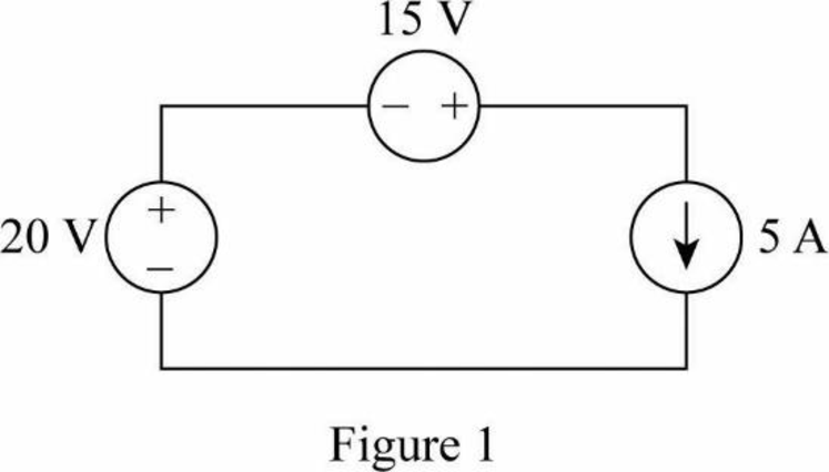
As the modified circuit in Figure 1 consists of all ideal independent sources, the interconnection of ideal sources in the modified circuit is valid.
From Figure 1, current of 5 A enters from the negative terminal of 20 V source. Therefore, 20 V voltage source develops the power.
Rewrite the expression in Equation (1) to find the power developed by the 20 V voltage source as follows:
From given circuit, the values of
Therefore, the power delivered by the 20 V voltage source is 100 W.
From the given circuit, current of 5 A enters from the negative terminal of 15 V source. Therefore, 15 V voltage source develops the power.
Rewrite the expression in Equation (1) to find the power developed by the 15 V voltage source as follows:
From given circuit, the values of
Therefore, the power developed by the 15 V voltage source is 75 W.
From the given circuit, the voltage drop across 5 A current source is calculated by using KVL to the circuit as follows:
Therefore, the voltage drop across 5 A current source is 35 V. That is, current 5 A enters the positive terminal and leaves from the negative terminal of 35 V voltage drop. Therefore, 5 A current source absorbs the power.
Rewrite the expression in Equation (1) to find the power absorbed by the 5 A current source as follows:
From given circuit, the values of
Therefore, the power absorbed by the 5 A current source is 175 W.
From the calculation, write the expression for power absorbed in the circuit as follows:
Substitute 175 W for
From the calculation, the power developed in the circuit as follows.
Substitute 100 W for
From the calculation, it is clear that the power absorbed in the circuit is equal to the power developed in the circuit.
Conclusion:
Thus, the interconnection of ideal sources in the modified circuit is valid, voltage source of 20 V and voltage source of 15 V are power developing sources and 5 A current source is a power absorbing source. The power absorbed in the modified circuit is equal to the power developed in the circuit.
Want to see more full solutions like this?
Chapter 2 Solutions
Electric Circuits (10th Edition)


 Introductory Circuit Analysis (13th Edition)Electrical EngineeringISBN:9780133923605Author:Robert L. BoylestadPublisher:PEARSON
 Delmar's Standard Textbook Of ElectricityElectrical EngineeringISBN:9781337900348Author:Stephen L. HermanPublisher:Cengage Learning
 Programmable Logic ControllersElectrical EngineeringISBN:9780073373843Author:Frank D. PetruzellaPublisher:McGraw-Hill Education
 Fundamentals of Electric CircuitsElectrical EngineeringISBN:9780078028229Author:Charles K Alexander, Matthew SadikuPublisher:McGraw-Hill Education
 Electric Circuits. (11th Edition)Electrical EngineeringISBN:9780134746968Author:James W. Nilsson, Susan RiedelPublisher:PEARSON
 Engineering ElectromagneticsElectrical EngineeringISBN:9780078028151Author:Hayt, William H. (william Hart), Jr, BUCK, John A.Publisher:Mcgraw-hill Education,