
Concept explainers
Videos
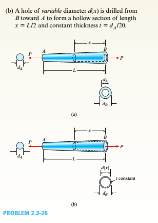
A uniformly tapered lube AB of circular cross section and length L is shown in the figure. The average diameters at the ends are dAand d£= 2d t. Assume E is constant. Find the elongation S of the tube when it is subjected to loads P acting at the ends. Use the following numerical data:^ = 35 mm, L = WO mm, E = 2.1 GPa. and P = 25 tN. Consider the following cases.
(a) A hole of constant diameter dAis drilled from B toward A to form a hollow section of length x - U2.
(b) A hole of variable diameter a\.x) is drilled, from B toward A to form a hollow section of length x = L/2 and constant thickness t = dA/20.
a.
The elongation of the tube when a hole of constant diameter dA is drilled from B to A to form a hollow section.
Answer to Problem 2.3.26P
The elongation of the tube when a hole of constant diameter dA is drilled from B to A to form a hollow section is 2.18 mm.
Explanation of Solution
Given:
From the given information, the area is calculated.
For the length
For the length x .
The elongation is calculated.
Given
Substituting the values:
Conclusion:
The elongation of the tube when a hole of constant diameter dA is drilled from B to A to form a hollow section is 2.18 mm.
b.
The elongation of the tube when a hole of variable diameter
Answer to Problem 2.3.26P
The elongation of the tube when a hole of variable diameter
Explanation of Solution
From the given information, the area is calculated.
For the length
For the length x .
The elongation is calculated.
Given
Substituting the values:
Conclusion:
The elongation of the tube when a hole of variable diameter
Want to see more full solutions like this?
Chapter 2 Solutions
Mechanics of Materials (MindTap Course List)


- A hollow circular tube T of a length L = 15 in. is uniformly compressed by a force P acting through a rigid plate (see figure). The outside and inside diameters of the tube are 3.0 and 2.75 in., respectively. A concentric solid circular bar B of 1.5 in. diameter is mounted inside the lube. When no load is present, there is a clearance c = 0.0I0 in. between the bar B and the rigid plate. Both bar and tube are made of steel having an c[autoplastic stress-strain diagram with E = 29 X LO3 ksi and err= 36 ksi. (a) Determine the yield load Pt- and the corresponding shortening 3yof the lube. (b) Determine the plastic load Ppand the corresponding shortening Spof the tube. (c) Construct a load-displacement diagram showing the load Pas ordinate and the shortening 5 of the tube as abscissa. Hint: The load-displacement diagram is not a single straight line in the region 0 ^ P ^ Prarrow_forwardA square steel tube of a length L = 20 ft and width b2= 10.0 in. is hoisted by a crane (see figure). The lube hangs from a pin of diameter d that is held by the cables at points A and B. The cross section is a hollow square with an inner dimension b1= 8.5 in. and outer dimension b2= 10,0 in. The allowable shear stress in the pin is 8,700 psi. and the allowable bearing stress between the pin and the tube is 13,000 psi. Determine the minimum diameter of the pin in order to support the weight of the tube. Note: Disregard the rounded corners of the tube when calculating its weight.arrow_forwardA uniformly tapered aluminum-ally tube AB of circular cross section and length L is fixed against rotation at A and B, as shown in the figure. The outside diameters at the ends are dAand dA.A hollow section of lenth L/2 and constant thickness t = dA/10 is cast into the tube and extends from B half-way toward A. Torque T0is applied at L/2. (a) Find the reactive torques at the supports, TA and TB. Use numerical values as follows: dA = 2.5 in., L = 48., G = 309 × 106 psi, and T0= 40,000 in.-lb. (b) Repeat part (a) if the hollow sections has constant diameter dA.arrow_forward
- Around brass bar of a diameter d1= 20mm has upset ends each with a diameter d2= 26 mm (see figure). The lengths of the segments of the bar are L1= 0.3 m and L2= 0.1 m. Quarter-circular fillets are used at the shoulders of the bar, and the modulus of elasticity of the brass is E = 100 GPa. If the bar lengthens by 0.12 mm under a tensile load P, what is the maximum stress ??maxin the bar?arrow_forwardA steel riser pipe hangs from a drill rig. Individual segments of equal length L = 50 ft are joined to get her using bolted flange plates (see figure part b). There are six bolts at each pipe segment connection. The outer and inner pipe diameters are t2= 14 in. and d1= 13 in.; flange plate thickness tf= 1.5 in.; and boll and washer diameters are db= 1.125 in. and dn. = 1.875 in. Find the number n of permissible segments of pipe based on following allowable stresses. (a) The allowable tensile stress in the pipe is 50 ksi. (b) The allowable tensile stress in a bolt is 120 ksi. Find number of segments n for two cases: pipe hanging in air and pipe hanging in seawater.arrow_forwardTwo pipe columns (AB, FC) are pin-connected to a rigid beam (BCD), as shown in the figure. Each pipe column has a modulus of E, but heights (L1or L2) and outer diameters (d1or different for each column. Assume the inner diameter of each column is 3/4 of outer diameter. Uniformly distributed downward load q = 2PIL is applied over a distance of 3L/4 along BC, and concentrated load PIA is applied downward at D. (a) Derive a formula for the displacementarrow_forward
- -21 Plastic bar AB of rectangular cross section (6 = 0.75 in. and h = 1.5 in.) and length L = 2 Ft is Fixed at A and has a spring support (Ar = 18 kips/in.) at C (see figure). Initially, the bar and spring have no stress. When the temperature of the bar is raised hy foot. the compressive stress on an inclined plane pq at Lq = 1.5 Ft becomes 950 psi. Assume the spring is massless and is unaffected by the temperature change. Let a = 55 × l0-6p and E = 400 ksi. (a) What is the shear stresst9 on plane pq? What is angle 07 =1 Draw a stress element oriented to plane pq, and show the stresses acting on all laces of this element. (c) If the allowable normal stress is ± 1000 psi and the allowable shear stress is ±560 psi, what is the maximum permissible value of spring constant k if the allowable stress values in the bar are not to be exceeded? (d) What is the maximum permissible length L of the bar if the allowable stress values in the bar are not be exceeded? (Assume £ = IB kips/in.) (e) What is the maximum permissible temperature increase (A7") in the bar if the allowable stress values in the bar are not to be exceeded? (Assume L = 2 ft and k = L& kips/inarrow_forwardA thin-walled circular tube and a solid circular bar of the same material (see figure) are subjected to torsion. The tube and bar have the same cross-sectional area and the same length. What is the ratio of the strain energy U1in the tube to the strain energy U2in the solid bar if the maximum shear stresses are the same in both cases? (For the tube, use the approximate theory for thin-walled bars.)arrow_forwardA hollow, circular, cast-iron pipe (Ec =12,000 ksi) supports a brass rod (Ec= 14,000 ksi} and weight W — 2 kips, as shown. The outside diameter of the pipe is dc= 6 in. (a) If the allowable compressive stress in the pipe is S00O psi and the allowable shortening of the pipe is 0.02 in., what is the minimum required wall thickness trmm? (Include the weights of the rod and steel cap in your calculations.) (b) What is the elongation of the brass rod Srdue to both load Wand its own weight? (c) What is the minimum required clearance h?arrow_forward
- A hollow circular tube having an inside diameter of 10.0 in, and a wall thickness of 1.0 in. (see figure) is subjected to a torque T = 1200 kip-in. Determine the maximum shear stress in the tube using (a) the approximate theory of thin-walled tubes, and (b) the exact torsion theory. Does the approximate theory give conservate or nonconservative results?arrow_forwardA retaining wall 6 ft high is constructed of horizontal wood planks 2.5 in. thick (actual dimension) that are supported by vertical wood piles of a 12 in, diameter (actual dimension), as shown in the figure. The lateral earth pressure is pt=125 lb/ft2 at the top of the wall and p2= 425 lb/ft2 at the bottom. Assuming that the allowable stress in the wood is 1175 psi, calculate the maximum permissible spacing s of the piles. Find the required diameter of the wood piles so that piles and planks (f = 2.5 in.) reach the allowable stress at the same time. Hint: Observe that the spacing of the piles may be governed by the load-carrying capacity of either the planks or the piles. Consider the piles to act as cantilever beams subjected to a trapezoidal distribution of load, and consider the planks to act as simple beams between the piles. To be on the safe side, assume that the pressure on the bottom plank is uniform and equal to the maximum pressure.arrow_forwardA steel riser pipe hangs from a drill rig located offshore in deep water (see figure). Separate segments are joined using bolted flange plages (see figure part b and photo). Assume that there are six bolts at each pipe segment connection. Assume that the total length of the riser pipe is L = 5000 ft: outer and inner diameters are d2= l6in.and d1= 15 in.; flange plate thickness t1= 1.75 in.; and bolt and washer diameters are db= 1.125 in..and dW. = 1.875 in., respectively. (a) If the entire length of the riser pipe is suspended in air. find the average normal stress a in each bolt, the average bearing stress abbeneath each washer, and the average shear stress t through the flange plate at each bolt location for the topmost bolted connection. (b) If the same riser pipe hangs from a drill rig at sea. what are the normal, bearing, and shear stresses in the connection? Obtain the weight densities of steel and sea water from Table I-1. Appendix I. Neglect the effect of buoyant foam casings on the riser pipearrow_forward
 Mechanics of Materials (MindTap Course List)Mechanical EngineeringISBN:9781337093347Author:Barry J. Goodno, James M. GerePublisher:Cengage Learning