
Videos
(a)
To plot:
A graph of
Answer to Problem 2.70HP
The plot of
Explanation of Solution
Calculation:
The formula to calculate the resistance
Substitute
Substitute
Substitute
Substitute
Substitute
Substitute
Substitute
Substitute
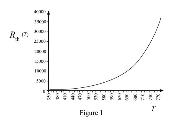
The plot of
The required diagram is shown in Figure 1
(b)
The expression for the equivalent resistance.
To plot:
A sketch of resistance
Answer to Problem 2.70HP
The expression for the equivalent resistance is
Explanation of Solution
Calculation:
The expression for the equivalent resistance is given by,
Substitute
Substitute
Substitute
Substitute
Substitute
Substitute
Substitute
Substitute
Substitute
Substitute
Substitute
Substitute
Substitute
Substitute
Substitute
Substitute
Substitute
Substitute
The plot for the equivalent resistance for different temperature ranges is shown in Figure 2
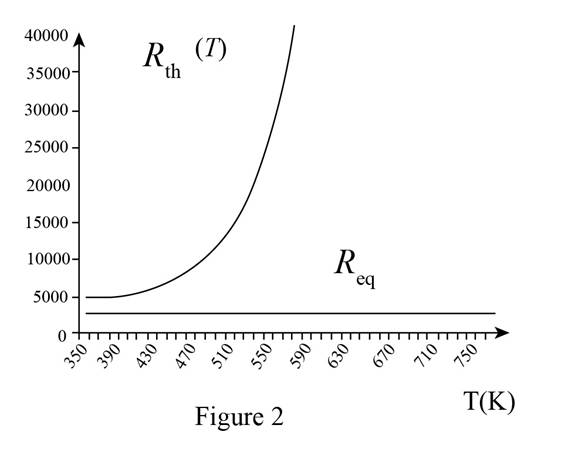
Conclusion:
Therefore, the expression for the equivalent resistance is
Want to see more full solutions like this?
Chapter 2 Solutions
Principles and Applications of Electrical Engineering


- For the figure shown below,1-Find the voltage labeled v at t = 0.2 ms .2 -Draw the circuits at t≤0 and t≥0.arrow_forward1. Theoretically calculate the voltage across the capacitor in the circuit of Figure 1 when t = 0 s, 5 s, 10 s, 20 s, 30 s, 40 s, and 60 s, assuming that the circuit is under DC conditions when t < 0 s and the switch is opened at t = 0 s. 2. Compare the calculated voltage at t = 20 s with the experimentally measured ∆?.arrow_forwardConsider the circuit in Figure 1. Determine analytically the time constant associated with the network shown in Figure 1, if R= 5.1 kΩ, and C= 0.1μF.arrow_forward
- In the circuit given below, the switch is closed at t <0 and the system works continuously. At t-0 the switch is opened, calculate the value of the voltage (Va) of point a at t = 1 ms.arrow_forwardthe initial energy stored in the circuit is zero. At t = Os the switch is closed and a DC current source of Is = 20mA is applied to the circuit. Given the following values: R = 100, L = 200mH, & C = 500gF. a) Calculate the step response IL (t) for t (greater than equalto) Os as a simplified numerical function of time b) sketch the plot for IL (t) for 0(less than euql to ) t (greater than equal to ) 100ms,arrow_forwardWe need to implement a simple voting system for a company. This company has a board composed of three directors having different voting weights as follows; a motion passes if it gets more than 50% of votes: Director A: 20% Director B: 30% Director C: 50% Design a circuit that implements this voting system. Supposing the output of the circuit is named V, in order to design this system you need to do the following: Make a truth table for V. [12%] Express V as a sum of products. [8%] Simplify V, either algebraically or by an explanation based upon the truth table. [15%] Draw the simplified circuit for V. [15%]arrow_forward
- "NORTON'S THEOREM" Please Find the Vo Using NORTONS’S THEOREM thankyou very much! I've included a cicruit app to check if your answer was correct and close to the value of currents and voltages which is 0.5V thankyou! I've been testing simple circuits to practice problems using different theorems,I appreciate you very much Thankyou!arrow_forward1. A 2.0 Ω resistor is connected to a non-ideal source with internal resistance equal to 1.0 Ω and EMF equal to 15V. If the potential measured by the voltmeter across the resistor is 10V, find the rate of electrical energy dissipation in the battery.arrow_forwardElectrical engineering A mesh collider a) is as accurate as the triangle count on the mesh b)is the variable optiom for complex meshes such as player characters c)is the only way to get headshots to work d)is faster than a box colliderarrow_forward
- A circuit having R = 25 Ω and L = 0.5 H is suddenly connected to a 250-v supply. Find the voltage across R at 1 time constant.arrow_forwardThe switch above the 12 V source in the circuit of Fig. below hasbeen closed for a long time. It is finally thrown open at t = 0. (a)Compute the circuit time constant. (b) Obtain an expression forv(t) valid for t > 0arrow_forwardSubject:Circuits IShow your solutions help me please so that i can learn tooarrow_forward
 Introductory Circuit Analysis (13th Edition)Electrical EngineeringISBN:9780133923605Author:Robert L. BoylestadPublisher:PEARSON
 Delmar's Standard Textbook Of ElectricityElectrical EngineeringISBN:9781337900348Author:Stephen L. HermanPublisher:Cengage Learning
 Programmable Logic ControllersElectrical EngineeringISBN:9780073373843Author:Frank D. PetruzellaPublisher:McGraw-Hill Education
 Fundamentals of Electric CircuitsElectrical EngineeringISBN:9780078028229Author:Charles K Alexander, Matthew SadikuPublisher:McGraw-Hill Education
 Electric Circuits. (11th Edition)Electrical EngineeringISBN:9780134746968Author:James W. Nilsson, Susan RiedelPublisher:PEARSON
 Engineering ElectromagneticsElectrical EngineeringISBN:9780078028151Author:Hayt, William H. (william Hart), Jr, BUCK, John A.Publisher:Mcgraw-hill Education,