
Concept explainers
Videos
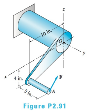
(a) Replace the force
(i)
The equivalent force couple vector acting at O.
Answer to Problem 2.91P
Explanation of Solution
Given Information:
F=-2800i+1600j+3000k
Concept used:
Conclusion:
(ii)
The resolved components of force R into normal component P and the shear component V.
Answer to Problem 2.91P
The normal component is 1600 lb.
The shear component is 4100 lb.
Explanation of Solution
Given:
F=-2800i+1600j+3000k
Concept Used:
Calculation:
Conclusion:
The normal component is 1600 lb.
The shear component is 4100 lb.
(iii)
The resolved components of Resultant couple CR into Torque component T and the bending moment component M.
Answer to Problem 2.91P
The torque component is 18800 lb-in.
The bending moment component is 36900 lb-in
Explanation of Solution
Given:
F=-2800i+1600j+3000k
Concept Used:
Calculation:
Conclusion:
The torque component is 18800 lb-in.
The bending moment component is 36900 lb-in.
Want to see more full solutions like this?
Chapter 2 Solutions
International Edition---engineering Mechanics: Statics, 4th Edition


- A hollow steel crank has an outside diameter of 26 mm and an inside diameter of 21 mm. The load magnitudes are Py = 690 N and Pz = 270 N, and the length dimensions are a = 145 mm, b = 399 mm, and c = 261 mm. Determine the magnitudes of the equivalent forces and the equivalent moments that act at the section that contains point K. (a) Axial force in x direction Px (N (b) Shear force in y direction Vy (N (c) Shear force in z direction Vz (N (d) Torque around x axis Tx (N·m) (e) Bending moment around y axis My (N·m) (f) Bending moment around z axis Mz (N·m) Calculate the section properties for the hollow crank at K. (g) Area A (mm2) (h) Polar moment of inertia J (mm4) (i) Area moment of inertia Iy (and Iz) (mm4) (j) QK (for shear force in y-direction) (mm3) Using the sign conventions, determine the normal and shear stresses that act at K and show these stresses on a stress element. (k) Normal stress in x direction σx(MPa) (l) Normal stress in y direction σy(MPa) (m) Shear stress in x-y…arrow_forwardA vertical load P = 800 lb applied to the tripod shown in the figure, causes a compressive force of 256 lb in leg AB and a compressive force of 283 lb in leg AC. Determine the force in leg AD and the coordinates xD and zD of its lower D. Answers: AD = 433 lb; xD = 4ft; zD = 1 ftarrow_forwardAn L-shaped bracket is supported by a frictionless pin at A and a cable between points B and D. If pin A is the origin, point C is at (-7, 0); and pin B is at (-7, -10). The cable is attached between point B and an anchor at point D, at (-2, -14). Units are in feet. Force F acts at point C at an angle of 60o from the positive x-axis. Determine the magnitude of the moment that the force F produces about point A. Determine the tension required to hold the bracket in position.arrow_forward
- The bar supported by a pin at B and a cable at A carries a load of 260 N at C. Neglecting the weight of the bar,a.) Determine the normal force 7 m from A.b.) Determine the shear force 7 m from A.c.) Determine the bending moment 7 m from Ad.) Determine the torsion 7 m from A SHOW COMPLETE SOLUTIONS DRAW FBDarrow_forwardThe peg shown at B is smooth. Member BC is loaded with a force P = 509.2 N and a moment of M = 808.7 N.m is applied at the pin A as shown in figure.  Determine the reaction at pin B in N. Determine the horizontal component of reaction at pin A in N. Determine the vertical component of reaction at pin A in N. Determine the horizontal component of reaction at the fixed support C in N. Determine the vertical component of reaction at the fixed support C in N. Determine the couple moment at the fixed support C in N.m.arrow_forward1. the tow truck's front wheels will belifted off the ground if the moment of the load W about the rear axle exceeds the moment of 3000N weight of the truck. Determine the largest w that may be safely applied 2. the flat plate shown in the figure is acted on by the three couples. replace the three couples with two forces, one acting along the line OParrow_forward
- In the assembly shown, member AB is rigidly attached to the wall while an L bar is pinned to AB at E. Two forces P and Q are acting on the assembly as shown. Force P lies on the x-axis while force Q is applied at point D along a plane parallel to the yz plane. 1. Which of the following quantities is/are zero? (Choices: A. Moment of P about the x-axis ; B. Moment of P about the y-axis ; C. Moment of P about the z-axis) 2. Which of the following best approximates the moment of force Q about point A? 3. Which of the following best approximates the equivalent force-couple set at point A of the applied forces P and Q? Note: F is the resultant force and Cis the resultant couple4. Considering the force diagram of member DE, which gives the complete set of reactions for the support at E? (Note difference of Force and couple reactions)arrow_forwardThe compound beam is supported by a roller at point C, fixed at point A, and the two sections are pinned at point B. It is subjected to a free couple moment M, a distributed load with maximum load intensity w, and a concentrated force F. If the distributed load w = 0.6 kN/m, the concentrated force F = 0.6 kN, and the free couple moment M = 0.8, determine the magnitude of the support reaction (in kN) at pin B. Answer must include 2 places after the decimal point.arrow_forwardP=197 KN L1= 1m L2= 1.4 m L3= 2 m L4= 4m a.) Determine the shear force at point D. b.) Determine the normal force at point D. c.) Determine the moment at point Darrow_forward
- Determine the internal forces at point D of the frame shown in the figure.arrow_forwardThe light boom AB is attached to a vertical wall by a ball and socket joint at A and supported by two cables at B. A force P is applied at B where P = 19i - 10j kN.Note that the reaction force at A acts along the boom because it is a two-force member. Magnitude of the reaction force at A in kN = 34.8 Determine the magnitude of the moment of P about the x-axis in Nmarrow_forwardA Pin spanner as shown in Figure, requires moment of 80 Nm to turn the 200 mm diameter shaft about its center O under the action of the applied force P. determine the contact reaction force on the smooth surface at the point A. Engagement of the pin at B may be considered to occur at the periphery of the collar OPTIONS:(MULTI CORRECT(MAY BE)): 1.Reaction at Point A is around 1047 N 2.Value of force P is around 102 N 3.Value of force P is around 133 N 4.Reaction at Point A is around 720 N 5.Reaction at Point A is around 1321 N 6.Value of force P is around 200 N 7.Value of force P is around 213 N 8.Reaction at Point A is around 970 Narrow_forward
 International Edition---engineering Mechanics: St...Mechanical EngineeringISBN:9781305501607Author:Andrew Pytel And Jaan KiusalaasPublisher:CENGAGE L
 Mechanics of Materials (MindTap Course List)Mechanical EngineeringISBN:9781337093347Author:Barry J. Goodno, James M. GerePublisher:Cengage Learning