
Concept explainers
Videos
Determine V in the circuit of Fig. 2.120.
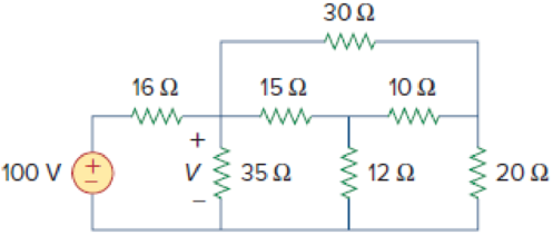
Figure 2.120
Calculate the value of voltage
Answer to Problem 56P
The value of voltage
Explanation of Solution
Formula used:
Consider the wye to delta conversions.
Here,
Consider the expression for
Here,
Consider the expression for
Calculation:
Refer to Figure 2.120 in the textbook For Prob.2.56.
Step 1:
From Figure 2.120, consider
Substitute
Substitute
Substitute
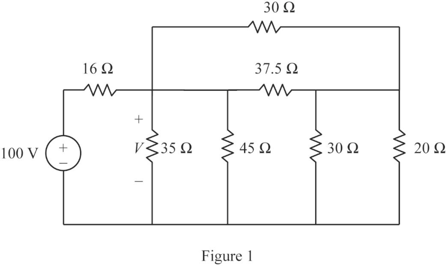
Modify Figure 2.120 as shown in Figure 1.
Step 2:
In Figure 1, as
Step 3:
In Figure 1, as
Step 4:
In Figure 1, as
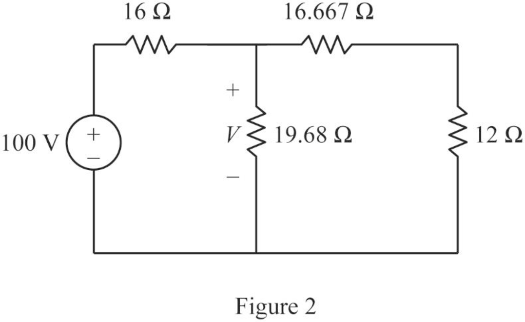
Modify Figure 1 as shown in Figure 2.
Step 5:
In Figure 2, as
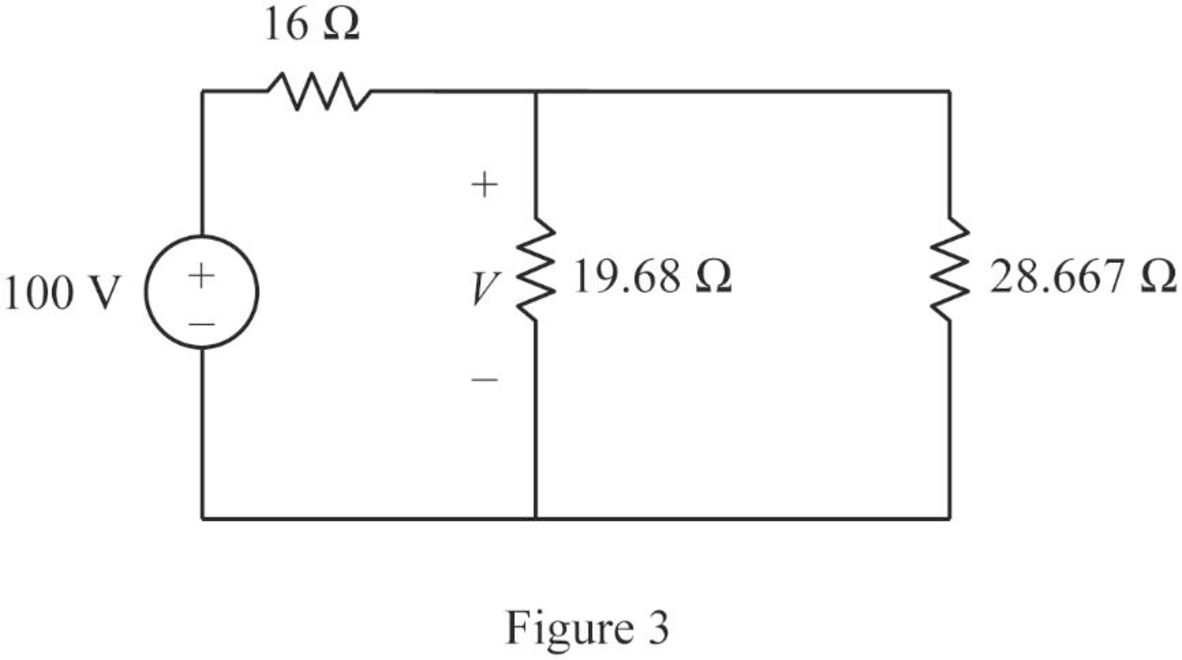
Modify Figure 2 as shown in Figure 3.
Step 6:
In Figure 3, as
Modify Figure 3 as shown in Figure 4.
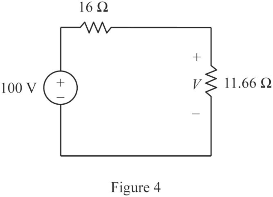
Step 7:
Apply voltage division rule to Figure 4.
Conclusion:
Thus, the value of voltage
Want to see more full solutions like this?
Chapter 2 Solutions
Fundamentals of Electric Circuits


- 2. Using mesh analysis, determine the voltage across the 10 kΩ resistor at terminals a-b of the circuit shown in Fig. 2.58.arrow_forward22. Determine the current i for the network shown in Fig. 2.48.arrow_forwardProblem 2 Consider the circuit in Fig. 2 and perform the following: Calculate the voltage across each resistor and the current through each branch of the circuit. (Using Ohm’s law, KCL and KVL) Verify that the law of conservation of energy is satisfied by showing that the algebraic sum of power is zero. Provide LTspice circuit simulation to confirm results found in parts (a) and (b).arrow_forward
- 10. State and explain Thevenin’s theorem. By applying Thevenin’s theorem or otherewise, find the cur- rent through the resistance R and the voltage across it when connected as shown in Fig. 2.178. [60.49 A, 600.49 V]arrow_forwardFrom fig.2, if a supply voltage of 16 V was connected across terminals A and B, computer for the overall power of the circuit.arrow_forwardFind the Norton equivalent circuit for the network external to the elements between a and b for the networks of Figure 2. all answers must be expressed in POLAR forms, and use 2 decimal places.arrow_forward
- 4. Find the equivalent Thevenin voltage and equivalent Thevenin resistance respectively as seen from open-circuited terminals A and B to the circuits shown in Fig. 2.173. All resistances are in ohms.arrow_forward7. Find the equivalent resistance between points A and B of the circuit shown in Fig. 2.198.arrow_forwardDetermine VL, IL, IZ and IR for the network Figure 2.183 if RL = 180Ω.arrow_forward
 Introductory Circuit Analysis (13th Edition)Electrical EngineeringISBN:9780133923605Author:Robert L. BoylestadPublisher:PEARSON
 Delmar's Standard Textbook Of ElectricityElectrical EngineeringISBN:9781337900348Author:Stephen L. HermanPublisher:Cengage Learning
 Programmable Logic ControllersElectrical EngineeringISBN:9780073373843Author:Frank D. PetruzellaPublisher:McGraw-Hill Education
 Fundamentals of Electric CircuitsElectrical EngineeringISBN:9780078028229Author:Charles K Alexander, Matthew SadikuPublisher:McGraw-Hill Education
 Electric Circuits. (11th Edition)Electrical EngineeringISBN:9780134746968Author:James W. Nilsson, Susan RiedelPublisher:PEARSON
 Engineering ElectromagneticsElectrical EngineeringISBN:9780078028151Author:Hayt, William H. (william Hart), Jr, BUCK, John A.Publisher:Mcgraw-hill Education,