Concept explainers
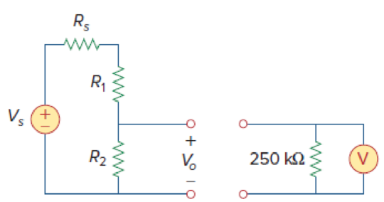
A voltmeter used to measure Vo in the circuit in Fig. 2.129. The voltmeter model consists of an ideal voltmeter in parallel with a 250-kΩ resistor. Let Vs = 95 V, Rs = 25 kΩ, and R1 = 40 kΩ. Calculate Vo with and without the voltmeter when
- (a) R2 = 5 kΩ
- (b) R2 = 25 kΩ
- (c) R2 = 250 kΩ

Figure 2.129
(a)
Find the values of
Answer to Problem 69P
The values of
Explanation of Solution
Given data:
Calculation:
Case 1: with voltmeter
Refer to Figure 2.129 in the textbook.
When a voltmeter is connected to the circuit,
By using voltage division rule, write the expression for voltage
Substitute
Substitute
Case 2: without voltmeter
As there is no voltmeter is connected, by directly using voltage law, write the expression for voltage
Substitute
Conclusion:
Thus, the values of
(b)
Find the values of
Answer to Problem 69P
The values of
Explanation of Solution
Given data:
Calculation:
Case 1: with voltmeter
Substitute
Substitute
Case 2: without voltmeter
Substitute
Conclusion:
Thus, the values of
(c)
Find the values of
Answer to Problem 69P
The values of
Explanation of Solution
Given data:
Calculation:
Case 1: with voltmeter
Substitute
Substitute
Case 2: without voltmeter
Substitute
Conclusion:
Thus, the values of
Want to see more full solutions like this?
Chapter 2 Solutions
Fundamentals of Electric Circuits
- Problem 2 Consider the circuit in Fig. 2 and perform the following: Calculate the voltage across each resistor and the current through each branch of the circuit. (Using Ohm’s law, KCL and KVL) Verify that the law of conservation of energy is satisfied by showing that the algebraic sum of power is zero. Provide LTspice circuit simulation to confirm results found in parts (a) and (b).arrow_forwardBasic Electrical Engineering A homeowner uses 100-watt incandescent lamps as a heater in an outside well pump house to protect the pump from freezing in cold weather. Unfortunately, however, the lamp can burn out and leave pump unprotected. You have been asked to install a hearth that will not burn out and leave the pump unprotected. You have available a 100-watt, 150-ohm wire-wound resistor. Can this resistor be connected to the 120-volt source without damage to the resistor? If so, what would be the power output of the resistor? (Hint: Use power formula)arrow_forward10. State and explain Thevenin’s theorem. By applying Thevenin’s theorem or otherewise, find the cur- rent through the resistance R and the voltage across it when connected as shown in Fig. 2.178. [60.49 A, 600.49 V]arrow_forward
- 11. State and explain Thevenin’s theorem. For the circuit shown in Fig. 2.179, determine the current through RL when its value is 50 Ω. Find the value of RL for which the power drawn from the source is maximum.arrow_forwardFor the network in Fig. 2 a. Convert the voltage source to a current source. b. Reduce the network to a single current source, and de- termine the voltage V1. c. Using the results of part (b), determine V2. d. Calculate the current I. + V2 - R2 2.2 kn 8 mA V,R6.8 kN 3 mA 18 V FIG. 2arrow_forward10. Use Superposition principle to find current in the 10-Ω resistor of Fig. 2.125. All resistances are in ohms. [1 A]arrow_forward
- 4. Use source transformation technique to find the current flowing through the 2 Ω resistor in Fig. 2.87 (b). [10 A]arrow_forwardA battery with a terminal voltage of Vab = 9 V is connected to a circuit having three 10-ohm and one 5-ohm resistors all in series. Assuming that the battery has negligible internal resistance, calculate the equivalent resistance in the circuit, and (b) the current through each resistor.arrow_forwardThe resistance of gold wire used in circuits is usually negligible compared to the components in the circuit, and can be ignored. For long, thin wires, this is no longer true. Calculate the resistance, in ohms, of a length of gold wire, 46.6 cm long, with a cross sectional area of 2.5 mm2. The resistivity of gold is 2.35×10⁻⁸ Ω.m. Use 2 significant figures in your answer.arrow_forward
- 7. Find the equivalent resistance between points A and B of the circuit shown in Fig. 2.198.arrow_forward25. Four resistance each of R ohms and two resistances each of S ohms are connected (as shown in Fig. 2.50) to four terminasl AB and CD. A p.d. of V volts is applied across the terminals AB and a resis- tance of Z ohm is connected across the terminals CD. Find the value of Z in terms of S and R in order that the current at AB may be V/Z. Find also the relationship that must hold between R and S in order that the p.d. at the points EF be V/2. [Z= R(R+2S);S=4R]arrow_forwardRenewable Energy Systems Homework 2 One type of PV module consists of 72 cells and the size of each cell is 0.125 m x 0.125 m. Theelectricity conversion efficiency of the module under standard test conditions is 14%. Estimate thepower output of one module and the number of modules required to generate 3 kW power at 962W/m2 insolation and 60oC cell temperature, assuming that the temperature coefficient of themodule power is 0.5%/oC. I'm preparing for the exam. Solutions requiredarrow_forward
 Introductory Circuit Analysis (13th Edition)Electrical EngineeringISBN:9780133923605Author:Robert L. BoylestadPublisher:PEARSON
 Delmar's Standard Textbook Of ElectricityElectrical EngineeringISBN:9781337900348Author:Stephen L. HermanPublisher:Cengage Learning
 Programmable Logic ControllersElectrical EngineeringISBN:9780073373843Author:Frank D. PetruzellaPublisher:McGraw-Hill Education
 Fundamentals of Electric CircuitsElectrical EngineeringISBN:9780078028229Author:Charles K Alexander, Matthew SadikuPublisher:McGraw-Hill Education
 Electric Circuits. (11th Edition)Electrical EngineeringISBN:9780134746968Author:James W. Nilsson, Susan RiedelPublisher:PEARSON
 Engineering ElectromagneticsElectrical EngineeringISBN:9780078028151Author:Hayt, William H. (william Hart), Jr, BUCK, John A.Publisher:Mcgraw-hill Education,


