
Concept explainers
Videos
For a specific application, the circuit shown in Fig. 2.140 was designed so that IL = 83.33 mA and that Rin = 5 kΩ. What are the values of R1 and R2?
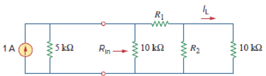
Figure 2.140
Calculate the values of
Answer to Problem 81CP
The values of
Explanation of Solution
Given Data:
Refer to Figure 2.140 in the textbook for the given circuit.
Formula used:
Consider the expression for
Here,
Consider the expression for
Calculation:
Modify Figure 2.140 as shown in Figure 1.
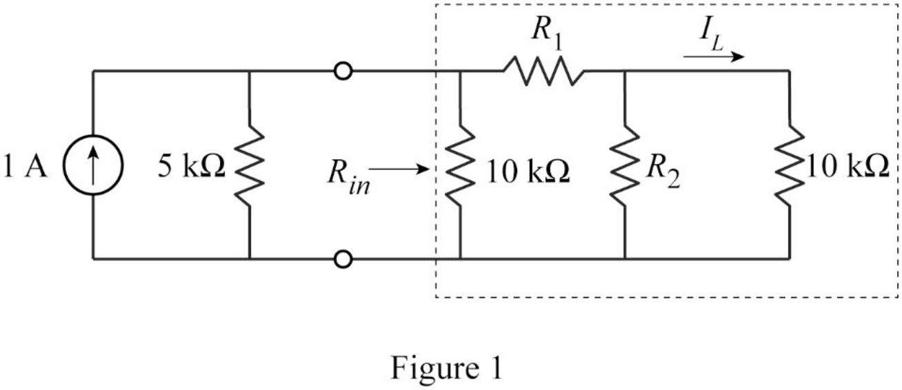
In Figure 1,
Therefore,
From Figure 1, write the expression for equivalent resistance
Substitute
To maintain
Modify the Figure as shown in Figure 2.
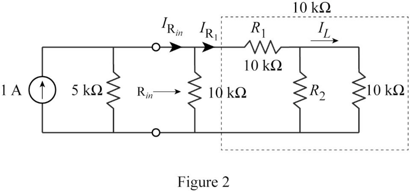
Therefore from current division rule, the current through
From current division rule, write the expression for current
Substitute
Rearrange the equation as follows.
Simplify the equation as follows.
Simplify the equation as follows.
Substitute
Simplify the equation as follows.
Simplify the equation to obtain the value of
Conclusion:
Thus, the values of
Want to see more full solutions like this?
Chapter 2 Solutions
Fundamentals of Electric Circuits


- 9. In the network shown in Fig. 2.177 find the current that would flow if a 2-Ω resistor was connected between points A and B by using.(a) Thevenin’s theorem and (b) Superposition theorem. The two batteries have negligible resistance. [0.82 A]arrow_forwardProblem 2 Consider the circuit in Fig. 2 and perform the following: Calculate the voltage across each resistor and the current through each branch of the circuit. (Using Ohm’s law, KCL and KVL) Verify that the law of conservation of energy is satisfied by showing that the algebraic sum of power is zero. Provide LTspice circuit simulation to confirm results found in parts (a) and (b).arrow_forward7. Find the equivalent resistance between points A and B of the circuit shown in Fig. 2.198.arrow_forward
- Basic Electrical Engineering A homeowner uses 100-watt incandescent lamps as a heater in an outside well pump house to protect the pump from freezing in cold weather. Unfortunately, however, the lamp can burn out and leave pump unprotected. You have been asked to install a hearth that will not burn out and leave the pump unprotected. You have available a 100-watt, 150-ohm wire-wound resistor. Can this resistor be connected to the 120-volt source without damage to the resistor? If so, what would be the power output of the resistor? (Hint: Use power formula)arrow_forward4. Use source transformation technique to find the current flowing through the 2 Ω resistor in Fig. 2.87 (b). [10 A]arrow_forwardA family of three is considering to install solar water heater system. Each person needs 50 liters of water per day. They require a hot water with temperature of 50 °C from using tap water as a source with a typical temperature of 20 °C. Calculate the required heat energy to satisfy the family demand in a year, and calculate the required area of flat plate collector (its efficiency 40% with energy gain 540 kWh.m-2/ year) and evacuated tube collector (its efficiency 60% with energy gain 800 kWh.m-2/ year) that needs to be installed. Describe your answer.arrow_forward
- 2. Convert the star circuit of Fig. 2.194 (b) into its equivalent delta circuit. Values shown are in ohms. Derive the formula used.arrow_forwardThe sun’s output power is given as 1000 W/m2. The solar module has a surface area of 1 m^2 with a conversion efficiency of 10%. A charge controller converts the 20V module voltage to 12V battery voltage, with an efficiency of 84% The battery is 12V with a capacity of 10Ah. Assuming the battery is half empty and the bulb is powered on, how long will it take for the battery to be fully charged? How long can the bulb be powered at night, assuming full battery when the sun goes down and that you can fully drain the batteryarrow_forward9. Using KCL, find the values V,p, 1, 1 and I, in the circuit of Fig. 2.43. All resistances are in ohms. (YAp=12 V ; 1, =2/3 A; L, = 1A; I, = 4/3 AIarrow_forward
 Introductory Circuit Analysis (13th Edition)Electrical EngineeringISBN:9780133923605Author:Robert L. BoylestadPublisher:PEARSON
 Delmar's Standard Textbook Of ElectricityElectrical EngineeringISBN:9781337900348Author:Stephen L. HermanPublisher:Cengage Learning
 Programmable Logic ControllersElectrical EngineeringISBN:9780073373843Author:Frank D. PetruzellaPublisher:McGraw-Hill Education
 Fundamentals of Electric CircuitsElectrical EngineeringISBN:9780078028229Author:Charles K Alexander, Matthew SadikuPublisher:McGraw-Hill Education
 Electric Circuits. (11th Edition)Electrical EngineeringISBN:9780134746968Author:James W. Nilsson, Susan RiedelPublisher:PEARSON
 Engineering ElectromagneticsElectrical EngineeringISBN:9780078028151Author:Hayt, William H. (william Hart), Jr, BUCK, John A.Publisher:Mcgraw-hill Education,