
Videos
For the battery of bulbs (purely resistive) appearing in Fig. 20.48 :
a. Determine the total power dissipation.
b. Calculate the total reactive and apparent power.
c. Find the source current Is.
d. Calculate the resistance of each bulb for the specified operating conditions.
e. Determine the currents I1 and I2.
(a)
The total power dissipation.
Answer to Problem 1P
The total power dissipated is
Explanation of Solution
Calculation:
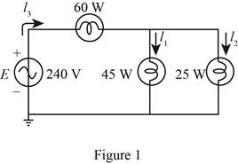
The given circuit diagram is shown in Figure 1.
The power dissipated in bulb 1 is
The total power dissipation is given by the sum of power dissipated in individual bulbs, that is,
Here,
Substitute
Conclusion:
Therefore, the total power dissipated is
(b)
The total reactive and apparent power.
Answer to Problem 1P
The reactive power dissipated in the bulbs is
Explanation of Solution
Calculation:
As the bulbs are purely resistive in nature therefore, the reactive power dissipated in bulb is zero that is,
The apparent power is given by,
Substitute
Conclusion:
Therefore, the reactive power dissipated in bulb is
(c)
The source current
Answer to Problem 1P
The source current
Explanation of Solution
Calculation:
The source voltage
The apparent power is given by,
Substitute
Conclusion:
Therefore, the source current
(d)
The resistance of each bulb.
Answer to Problem 1P
The resistance of bulb 1 is
Explanation of Solution
Calculation:
The power dissipated in first bulb is given by,
Substitute
The voltage
Substitute
From the figure 1 it can be seen that voltage
Substitute
The power dissipated in bulb 2 is given by,
Substitute
The power dissipated in bulb 3 is given by,
Substitute
Conclusion:
Therefore, the resistance of bulb 1 is
(e)
The current
Answer to Problem 1P
The current
Explanation of Solution
Calculation:
The value of current
Substitute
The current
Substitute
Conclusion:
Therefore, the current
Want to see more full solutions like this?
Chapter 20 Solutions
Introductory Circuit Analysis (13th Edition)
Additional Engineering Textbook Solutions
Fundamentals of Electric Circuits
Microelectronics: Circuit Analysis and Design
ELECTRICITY FOR TRADES (LOOSELEAF)
Programmable Logic Controllers
ANALYSIS+DESIGN OF LINEAR CIRCUITS(LL)
Electronics Fundamentals: Circuits, Devices & Applications


- Compute the power factor and the reactive factorfor the network inside the box in Fig. 10.6,whose voltage and current are described inExample 10.1.Hint: Use -i to calculate the power and reactivefactorsarrow_forwardExplore advanced strategies for energy storage and their significance in improving the reliability and stability of modern power systems.arrow_forwardGive the instantaneous voltage voltages of each of the following angles, if we have a 100v source as peak value20°40°80°220°arrow_forward
- Estimate the utilization factor, if the maximum demand is 480 W and rated capacity is 500 W.arrow_forwardIt has been desired to install a diesel power station to supply power in a suburban area having the following particulars: (i) 1000 houses with average connected load of 1.5 kW in each house. The demand factor and diversity factor being 0.4 and 2.5 respectively. (ii) 10 factories having overall maximum demand of 90 kW. (iii) 7 tubewells of 7 kW each and operating together in the morning. The diversity factor among above three types of consumers is 1.2. What should be the minimum capacity of power station?arrow_forwardFor the circuit shown,a) To the coil of a henry, measure its internal resistance and the value of the inductance.b) Measure the effective voltage and current at the terminals of the 100 Ω resistor and at the source.c) Measure the average power delivered by the source.Note the phase shift between the supply voltage and the voltage across the 100 Ω resistor (only at this point).arrow_forward
- Feedwater economizer can recover up to 12% waste heat? Select one: True Falsearrow_forwardPlease do not copy other side give proper calculation In an office building there are 20 such rooms, as mentioned. There is also a smart electric meter to display and record the instantaneous power demand of the whole building. The maximum/peak reading of the meter in a year is found to be 66666.66 W. Assuming that the maximum reading of the meter placed in each room is same, i.e., 4000 W. Determine the diversity factor of the building’s load.arrow_forwardA 50-liter hot-water tank is used in the laundry service of a hospital clinic. The water in the tank is heated up using an electrical heater that is operated from 200V (mains) power line. The heater draws 5 A from the mains. Assume that the thermal resistance of the tank is Rt=0.04 ℃/W. The temperature of the tap water is 10 ℃. How much is the maximum temperature of the water in the tank in the steady state?arrow_forward
- An 80-gallon electric water heater has 60F (15.56C) incoming water. How many minutes can a 3-gallon/minute showerhead be used to draw 105F (40.56C) water if the water heater thermostat is set at 120F (48.89C)?arrow_forwardist out all the major components in a thermal power plantarrow_forwardA fan rated at 4.45kW blows 250 cubic meter /min of air through a 750kW motor to carry away the heat. If the inlet temperature is 22°C and the outlet temperature is 31°C, estimate the losses in the motor.arrow_forward
 EBK ELECTRICAL WIRING RESIDENTIALElectrical EngineeringISBN:9781337516549Author:SimmonsPublisher:CENGAGE LEARNING - CONSIGNMENT