
Concept explainers
Videos
The rod ABC is made of an aluminum for which E = 70 GPa. Knowing that P = 6 kN and Q = 42 kN, determine the deflection of (a) point A, (b) point B.
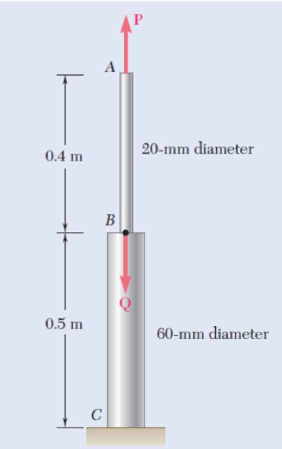
Fig. P2.19 and P2.20
a)
The deflection of the point A
Answer to Problem 20P
The deflection of the point A
Explanation of Solution
Given information:
The Young’s modulus of the aluminium (E) is
The force at the point A (P) is
The force at the point B (Q) is
The diameter of the rod AB
The diameter of the rod BC
The length of the rod AB
The length of the rod BC
Calculation:
Calculate the cross-sectional area of the rod AB
Substitute
Calculate the cross-sectional area of the rod BC
Substitute
Calculate the defection of the rod AB
Substitute
Calculate the defection of the rod BC
Substitute
Calculate the deflection of the point A
Substitute
Hence, the deflection of the point A
b)
The deflection of point the B
Answer to Problem 20P
The deflection of the B
Explanation of Solution
Given information:
The Young’s modulus of the aluminium (E) is
The force at the point A (P) is
The force at the point B (Q) is
The diameter of the rod AB
The diameter of the rod BC
The length of the rod AB
The length of the rod BC
Calculation:
Calculate the cross-sectional area of the rod AB
Substitute
Calculate the cross-sectional area of the rod BC
Substitute
Calculate the defection of the rod AB
Substitute
Calculate the defection of the rod BC
Substitute
The deflection of the point B
Therefore, the deflection of the point B
Want to see more full solutions like this?
Chapter 2 Solutions
Mechanics of Materials, 7th Edition


- The length of the 332332 -in.-diameter steel wire CD has been adjusted so that with no load applied, a gap of 116116 in. exists between the end B of the rigid beam ACB and contact point E. Knowing that E = 29 × 106 psi, determine where a 57-lb (w) block should be placed on the beam in order to cause contact between B and E. For contact, x < in.arrow_forwardThe 981-kg uniform bar AB is suspended from two cables AC and BD each with cross-sectional area 339 mm2. Find the location x (in mm) of P that can be safely applied to the bar if the stresses in AC and BD are limited to 119 MPa and 52 MPa, respectively. Express your answer in two decimal places.arrow_forwardA rod hanging from a support whose unit mass is 3900 kg/ m3 has a cross-sectional area of 400 mm2 and 250 meters long. If the load of 18 kN is applied at its free end and E = 200 x 103 MPa, determine, a) Elongation due to its ownweight in mm, b) Elongation due to the applied load in mm and c) Total elongation in mm.arrow_forward
- The 1021-kg uniform bar AB is suspended from two cables AC and BD each with cross-sectional area 472 mm2. Find the magnitude of P (in N) that can be safely applied to the bar if the stresses in AC and BD are limited to 110 MPa and 51 MPa, respectively. Express your answer in two decimal places.arrow_forward2.15 A single axial load of magnitude P = 58 kN is applied at end C of the brass rod ABC. Knowing that E = 105 GPa, determine the diam- eter d of portion BC for which the deflection of point C will be 3 mm. 30 mm 1.2 m Fig. P2.15 B -0.8 m Note:- • Do not provide handwritten solution. Maintain accuracy and quality in your answer. Take care of plagiarism. • Answer completely. • You will get up vote for sure.arrow_forwardA 4-ft section of aluminum pipe of cross-sectional area 1.75 in2 rests on a fixed support at A. The 58-in.-diameter steel rod BC hangs from a rigid bar that rests on the top of the pipe at B. Knowing that the smodulus of elasticity is 29 3 106 psi for steel and 10.4 3 106 psi for aluminum, determine the deflection of point C when a 15-kip force is applied at C.arrow_forward
- Q1 / Two solid cylindrical rods are joined at B and loaded as shown. Rod AB is made GPa) and rod BC of brass (E = 105 GPa). Determine (a) the total deformation of the composite rod ABC, (b) the deflection of point B.arrow_forwardBoth portions of the rod ABC are made of an aluminum for which E = 70.4GPa. Knowing that the magnitude of Q is 31876 N, m = 0.35 m, and n = 0.55 m, determine the value of P (in N) so that the deflection at A is zero.arrow_forwardThe cylindrical bar composed of two parts (AB and BC) is fixed at ends A and C. The two parts are made of different materials with different cross-sections. An external load ? =28 kN is applied at point B. The cross-sectional area of AB and BC part is 0.9 cm2and 0.3 cm2, respectively. The modulus of elasticity of the AB and BC part is 40 GPa and 200 GPa, respectively. Determine the force reactions at ends A and C.arrow_forward
- A 13-mm-diameter steel (E = 193 GPa) rod (2) is connected to a 27-mm-wide by 10-mm-thick rectangular aluminum (E = 72 GPa) bar (1), as shown. Assume L1 = 0.74 m and L2 = 1.38 m. Determine the force P (in kN rounded to the nearest tenths) required to stretch the assembly 8.1 mm.arrow_forwardEach of the three aluminum bars shown is to be twisted through an angle of 2.1°. Knowing that b = 30 mm, τall = 50 MPa, and G = 27 GPa, determine the shortest allowable length of each bar. Refer to Table 3.1. The shortest allowable length of bar (a) is mm. The shortest allowable length of bar (b) is mm. The shortest allowable length of bar (c) is mm.arrow_forwardThe rod ABC is made of an aluminum for which E = 71.15 GPa. Knowing that P=10.2 kN and Q=51.62kN, determine the deflection (in um) of point B y=0.46 and z=0.56. Round off the final answer in four decimal places.arrow_forward
 Elements Of ElectromagneticsMechanical EngineeringISBN:9780190698614Author:Sadiku, Matthew N. O.Publisher:Oxford University Press
 Mechanics of Materials (10th Edition)Mechanical EngineeringISBN:9780134319650Author:Russell C. HibbelerPublisher:PEARSON
 Thermodynamics: An Engineering ApproachMechanical EngineeringISBN:9781259822674Author:Yunus A. Cengel Dr., Michael A. BolesPublisher:McGraw-Hill Education
 Control Systems EngineeringMechanical EngineeringISBN:9781118170519Author:Norman S. NisePublisher:WILEY
 Mechanics of Materials (MindTap Course List)Mechanical EngineeringISBN:9781337093347Author:Barry J. Goodno, James M. GerePublisher:Cengage Learning
 Engineering Mechanics: StaticsMechanical EngineeringISBN:9781118807330Author:James L. Meriam, L. G. Kraige, J. N. BoltonPublisher:WILEY