
Concept explainers
Videos
A magnet is hung by a string and then placed near a wire as shown. When the switch is closed, the magnet rotates such that the ends of the magnet move as indicated by the arrows.
At instant the switch is closed determine:
- the direction of the current through the wire segment nearest the magnet. Explain.
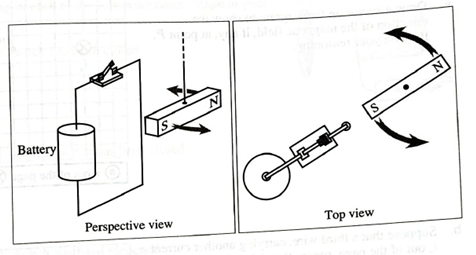
The direction of the current through the wire segment nearest to the magnet and direction of the net force exerted by the magnet on the wire segment at the instant when the magnet is in its normal position with their explanation.
Explanation of Solution
Introduction:
According to Fleming’s right-hand rule, the first finger, second finger and thumb are held at a right angle to each other, then the forefinger will represent the direction of the line of force. The thumb will point the direction of the motion and the second finger will give the direction of the induced current.
The expression of the magnetic force is given by the following expression,
Here,
Case-1
When the switch is closed, the magnetic north of the magnet moves towards the circuit which implies that the induced current in the wire tends to deflect the magnet towards the right side. With the application of Fleming’s right hand, the anti-clockwise current can produce the magnetic field which is opposite to the magnetic south of the magnet and the direction of the induced current will be in the upward direction. The direction of the current and the magnetic field is shown in Figure 1.
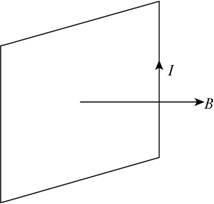
Figure 1
Consider the direction of the current represented by the
Figure 2
This implies that the direction of the force acting on the wire segment is towards the right.
Conclusion:
Therefore, the direction of the current through the segment near the magnet is up and the direction of the current in the wire is anticlockwise and the direction of the force acting on the wire segment is towards the right.
Want to see more full solutions like this?
Chapter 21 Solutions
Tutorials in Introductory Physics
Additional Science Textbook Solutions
Cosmic Perspective Fundamentals
Sears And Zemansky's University Physics With Modern Physics
University Physics (14th Edition)
Life in the Universe (4th Edition)
Introduction to Electrodynamics


- The right half of the square loop of wire shown in (Figure 1) is in a 0.85 T magnetic field directed into the page. The current in the loop is 1.1 A in a clockwise direction. 1. What is the magnitude of the force on the loop? Express your answer with the appropriate units. 2. In which direction does this force act? A. to the left B. upward C. downward D. to the rightarrow_forwardA particle of mass “M” and charge “+Q” Travels at a velocity “V” in a plane perpendicular to a Magnetic Field of magnitude “B” as shown in the Picture. The particle will experience motion on a circular path. (not the question just context, also the pic is for probelm 1.) Assume similar conditions as problem 1 but now the proton, moves along the magnetic field undeflected. This new behavior can only be explained if there exist an external electric field in addition to the magnetic field. What is the magnitude and direction of such field? (you can disregard gravity) (prob 2 is the question:) sorry if its confusing)arrow_forwardUsing the Right-Hand Rule, determine the direction of the magnetic force on a negative charge moving in a uniform magnetic field as shown in the diagrams A-C below.Will the results on each case be the same if the charge is positive? How?arrow_forward
- A rod of mass m and resistance R slides without friction in a horizontal plane, movingon parallel rails as shown in Figure 4. The rails are separated by a distance d. A battery that maintainsa constant emf ε is connected between the rails, and a constant magnetic field B is directed out of thepage. Assuming the rod starts from rest at time t = 0, find its velocity in terms of time t, ε, B, d, m,and R.arrow_forwardA metal wire of mass m slides without friction on two horizontal rails spaced a distance d apart, as in the figure below. The track lies in a vertical uniform magnetic field . Generator G produces a constant current i in the wire and the rails (even as the wire moves). Find the velocity of the wire's motion as a function of time, assuming it to be stationary at t = 0. (Use any variable or symbol stated above along with the following as necessary: B for the magnitude of . All quantities are in SI units. Enter the sign of the expression, taking right to be positive.)arrow_forwardFigure 3 shows a straight wire carrying a current in upwarddirection. The wire is placed near a wire loop. For each case described below, answer the following questions:a. What is the direction of the magnetic flux through theloop?b. Is the magnitude of the flux through the loop increasing ordecreasing with time?c. What is the direction of the magnetic field produced by theinduced current in the loop?d. What is the direction of the current induced in the loop?1. Case 1: The current is increasing.2. Case 2: The current is decreasing.3. Case 3: The current is constant but the loop is being pulledaway from the straight wire.arrow_forward
- In the diagram above, a bar magnet is brought closer to a conducting wire loop with 7 Ω of resistance. As a result a uniform 3 A current is induced in the wire. What is the direction of the induced magnetic field at the center of the loop? Explain the reasoning behind your selection in detail.A) UpB) DownC) ClockwiseD) CounterclockwiseE) Cannot be determinedarrow_forwardConsider a system made up of two semicircular loops, one of radius ? and the other of major radius ? that carries a current ? in a clockwise direction; in addition, a straight wire, of great length, which is placed as shown in the figure. Calculate: 1. the magnetic field produced by the coil system at its center. 2. The intensity and direction of the current that must pass through the vertical straight wire to the magnetic field at the center of the loop is zero. Give your answer in terms of ?, ? and ?.arrow_forwardpls help me with the following question and make sure is 100% correct, pls and thank you A long wire carrying I� = 6.95 AA of current makes two bends, as shown in (Figure 1). The bent part of the wire passes through a uniform 0.290 TT magnetic field directed as shown in the figure and confined to a limited region of space. Part A. Find the magnitude of the force that the magnetic field exerts on the wire. Express your answer in newtons. Part B Find the direction of the force that the magnetic field exerts on the wire. Give your answer as a clockwise angle in degrees from the left-hand straight segment.arrow_forward
- Hi please help: A single current-carrying circular loop of radius R is placed next to a long, straight wire, as shown below. The current in the wire points to the right and is of magnitude I. In which direction must the current flow in the loop to produce zero magnetic field at its center? Explainarrow_forwardConsider the system pictured as shown. A 15.0-cm horizontal wire of mass 15.0 g is placed between two thin, vertical conductors, and a uniform magnetic field acts perpendicular to the page. The wire is free to move vertically without friction on the two vertical conductors. When a 5.00-A current is directed as shown in the figure, the horizontal wire moves upward at constant velocity in the presence of gravity. (a) What forces act on the horizontal wire, and (b) under what condition is the wire able to move upward at constant velocity? (c) Find the magnitude and direction of the minimum magnetic field required to move the wire at constant speed. (d) What happens if the magnetic field exceeds this minimum value?arrow_forwardHi please help:A single current-carrying circular loop of radius R is placed next to a long, straight wire, as shown below. The current in the wire points to the right and is of magnitude I. Find the direction that the current must flow in the loop to produce zero magnetic field at its center and calculate the magnitude of the current. Express answer in terms of some or all of variables R, I, and appropriate constants.arrow_forward

 Glencoe Physics: Principles and Problems, Student...PhysicsISBN:9780078807213Author:Paul W. ZitzewitzPublisher:Glencoe/McGraw-Hill