
Concept explainers
Videos
Bar AB has a cross-sectional area of 1200 mm2 and is made of a steel that is assumed to be elastoplastic with E = 200 GPa and σY = 250 MPa. Knowing that the force F increases from 0 to 520 kN and then decreases to zero, determine (a) the permanent deflection of point C, (b) the residual stress in the bar.
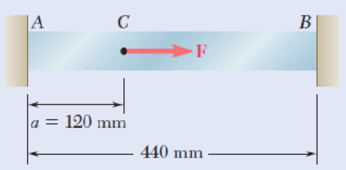
Fig. P2.122
(a)
The permanent deflection of point C.
Answer to Problem 122P
The permanent deflection of point C is
Explanation of Solution
Given information:
The cross sectional area A of section AB is
The modulus of elasticity E is
The yield stress
The force F is
Calculation:
Determine the force at yield portion AC using the relation:
Substitute
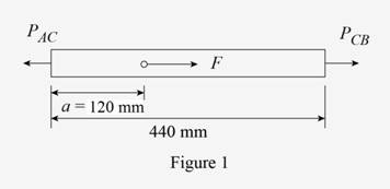
Sketch the bar ACB as shown in Figure 1.
Find the load
Substitute
Find the length
Refer to Figure 1.
Find the deflection at point C using the relation:
Here,
Substitute
Find the stress in rod along CB using the relation:
Substitute
Show the expression of deflection at point C for unloading to find the load
Here,
Substitute
Find the load
Substitute
Calculate the stress at point along AC using the relation:
Substitute
Calculate the stress at point along BC using the relation:
Substitute
Determine the deflection at point C using the relation:
Substitute
Determine the permanent deflection at point C using the relation:
Substitute
Thus, the permanent deflection of point C is
(b)
Find the residual stress in bar AC and CB.
Explanation of Solution
The residual stress in bar AC is
The residual stress in bar CB is
Calculation:
Find the residual stress in bar AC using the relation:
Substitute
Thus, the residual stress in bar AC is
Find the residual stress in bar BC using the relation:
Substitute
Thus, the residual stress in bar CB is
Want to see more full solutions like this?
Chapter 2 Solutions
Mechanics of Materials, 7th Edition


- The length of the 332332 -in.-diameter steel wire CD has been adjusted so that with no load applied, a gap of 116116 in. exists between the end B of the rigid beam ACB and contact point E. Knowing that E = 29 × 106 psi, determine where a 57-lb (w) block should be placed on the beam in order to cause contact between B and E. For contact, x < in.arrow_forwardRigid bar ABC is supported by bronze rod (1) and aluminum rod (2), as shown. A concentrated load P is applied to the free end of aluminum rod (3). Bronze rod (1) has an elastic modulus of E1 = 15,000 ksi and a diameter of d1 = 0.50 in. Aluminum rod (2) has an elastic modulus of E2 = 10,000 ksi and a diameter of d2 = 0.85in. Aluminum rod (3) has a diameter of d3 = 1.00in. The yield strength of the bronze is 48 ksi and the yield strength of the aluminum is 40 ksi. Assume a = 2.5 ft, b = 1.5 ft, L1 = 6 ft, L2 = 8 ft, and L3 = 3 ft. (A) Calculate the cross-sectional areas of the three rods. in in.2 (B) For a factor of safety of 2.1, calculate the allowable stresses in the bronze and the aluminum rods. IN KSI. (C) What is the magnitude of load P that can safely be applied to the structure for a minimum factor of safety of 2.1? in kips (D) The pin used at B has an ultimate shear strength of 58 ksi. If a factor of safety of 2.5 is required, determine the allowable shear stress in this pin.…arrow_forwardKnowing that a 0.02-in. gap exists when the temperature is 75°F, determine (a) the temperature at which the normal stress in the alumi-num bar will be equal to –11 ksi, (b) the corresponding exact length of the aluminum bar.arrow_forward
- The normal strain in a suspended bar of material of varying cross section due to its own weight is given by the expression γy/3E where γ = 2.9 lb/in.3 is the specific weight of the material, y = 3.4 in. is the distance from the free (i.e., bottom) end of the bar, L = 17 in. is the length of the bar, and E = 24000 ksi is a material constant. Determine, (a) the change in length of the bar due to its own weight. (b) the average normal strain over the length L of the bar. (c) the maximum normal strain in the bar.arrow_forwardA 10-mm diameter steel bolt is surrounded by bronze sleeve. The outer diameter of the bronze sleeve is 20 mm and its inner diameter is 10-mm. Given that the yield stress for the steel is 640 MPa and the yield stress for the bronze is 520 MPa, determine the magnitude of the maximum allowable total load that can be applied to this assembly. (Assume full bond between the steel and the bronze sleeve) Esteel = 200 GPa, Ebronze = 100 GPa, Factor of safety = 1.5arrow_forwardA force of 5 KN is exerted on a 6 mm diameter brass rod. Determine the percentage increase of its length if the modulus of elasticity of brass is 90 GPa.arrow_forward
- Rigid bar ABC is supported by bronze rod (1) and aluminum rod (2), as shown. A concentrated load P is applied to the free end of aluminum rod (3). Bronze rod (1) has an elastic modulus of E1 = 15,000 ksi and a diameter of d1 = 0.40 in. Aluminum rod (2) has an elastic modulus of E2 = 10,000 ksi and a diameter of d2 = 0.70in. Aluminum rod (3) has a diameter of d3 = 1.00in. The yield strength of the bronze is 48 ksi and the yield strength of the aluminum is 40 ksi. Assume a = 2.5 ft, b = 1.5 ft, L1 = 6 ft, L2 = 8 ft, and L3 = 3 ft.arrow_forward2 m long aluminium rod must not stretch more than 1 mm and the normal stress must not exceed 38 MPa when the rod is subjected to a 5 kN axial load. Knowing that Modulus of Elasticity for Aluminium (E)= 70 GPa, determine the required diameter of the rod. D= 13.49 mmarrow_forward6. A strain gage located at C on the surface of bone AB indicates that the average normal stress in the bone is 3.80 MPa when the bone is subjected to two 1200-N forces as shown. Assuming the cross section of the bone at C to be annular and knowing that its outer diameter is 25 mm, determine the inner diameter of the bone’s cross section at C.arrow_forward
- When subjected to a compressive load, the length of the rod is 199,6 mm, and its diameter is 10 mm. If the original length was 200 mm, and modulus is 70 GPa, determine: 1.1 The stress and strain in the rod when loaded. 1.2 The magnitude of the load.arrow_forwardThe aluminum rod AD is fitted with a jacket that is used to apply a hydrostatic pressure of 6000 psi to the 12-in. portion BC of the rod. Knowing that E=10.1* 106 psi and ν=0.36, determine (a) the change in the total length AD, (b) the change in diameter at the middle of the rod, determine the forces that should be applied to the ends A and D of the rod (a) if the axial strain in portion BC of the rod is to remain zero as the hydrostatic pressure is applied, (b) if the total length AD of the rod is to remain unchangedarrow_forwardA timber beam AB of length L and rectangular cross section carries a single concentrated load P at its midpoint C. (a) Show that the ratio Tm/ m of the maximum values of the shearing and normal stresses in the beam is equal to h/2L, where h and L are, respectively, the depth and the length of the beam. (b) Determine the depth h and the width b of the beam, knowing that L = 2 m, P = 40 kN, 7m = 960 kPa, and om = 12 MPa.arrow_forward
 Elements Of ElectromagneticsMechanical EngineeringISBN:9780190698614Author:Sadiku, Matthew N. O.Publisher:Oxford University Press
 Mechanics of Materials (10th Edition)Mechanical EngineeringISBN:9780134319650Author:Russell C. HibbelerPublisher:PEARSON
 Thermodynamics: An Engineering ApproachMechanical EngineeringISBN:9781259822674Author:Yunus A. Cengel Dr., Michael A. BolesPublisher:McGraw-Hill Education
 Control Systems EngineeringMechanical EngineeringISBN:9781118170519Author:Norman S. NisePublisher:WILEY
 Mechanics of Materials (MindTap Course List)Mechanical EngineeringISBN:9781337093347Author:Barry J. Goodno, James M. GerePublisher:Cengage Learning
 Engineering Mechanics: StaticsMechanical EngineeringISBN:9781118807330Author:James L. Meriam, L. G. Kraige, J. N. BoltonPublisher:WILEY