
Concept explainers
Videos
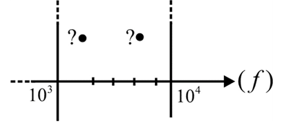
- Determine the frequencies (in kHz) at the points indicated on the plot in Fig. 22.104(a).
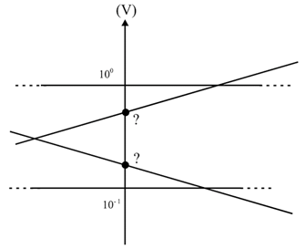
- Determine the voltages (in mV) at the points indicated on the plot in Fig. 22.104(b).
(a)
The frequencies at the points indicated in the plot
Answer to Problem 1P
The frequencies at the points are
Explanation of Solution
Given:
Formula used:
The frequency at the point is calculated by
Calculation:
The distance of the first point,
The distance between two vertical axes is
The value of the first point,
The value of the first point is
The values of the second point is,
The value of the second point is
Conclusion:
Thus, the value of the first point is
(b)
The voltages at the points indicated on the plot
Answer to Problem 1P
The voltage of the top point is 527.5mVand the bottom point is 181.7mV
Explanation of Solution
Given:
Formula used:
The voltage at the point is calculated by
Calculation:
The total length of the vertical axis is,
Using a scale on the vertical axis, from the plot, we can find that the top and bottom points are at a fractionof total length of the vertical axis from the bottom.
The voltage value of the top point is
The voltage of the top point is 527.5mV
The voltage value of the bottom point is
The voltage of the bottom point is 181.7mV
Conclusion:
Thus, the voltage of the top point is 527.5mVand the voltage of the bottom point is 181.7mV
Want to see more full solutions like this?
Chapter 22 Solutions
Introductory Circuit Analysis (13th Edition)
Additional Engineering Textbook Solutions
Fundamentals of Applied Electromagnetics (7th Edition)
Electric Circuits. (11th Edition)
Loose Leaf for Engineering Circuit Analysis Format: Loose-leaf
Electronics Fundamentals: Circuits, Devices & Applications
Electrical Engineering: Principles & Applications (7th Edition)
Programmable Logic Controllers


- Given the measured value of VD, Determine: a. ID b. VDS c. VGGarrow_forwardQ/ Explain the effects of the filters & the noise source.arrow_forwardA transmitter with an output power of 50 W is connected to a matched load by 32 m of matched coaxial cable. It is found that only 35 W of power is dissipated in the load. Calculate the loss in the cable in decibels per 100 meters.arrow_forward
- An amplifier, having a temperature of 30 K is placed in a microwave environment with a noise temperature of 40 K. Estimate the available noise power per unit bandwidth.arrow_forwardA 110 Volts supply with a current of 200 mA is connected in an antenna input of a radio receiver. The bandwidth of the receiver is 30 Mhz and the resistor at temperature of 65 degrees Farenheit. Find the Noise Power and Noise Voltage applied to the receiver input.arrow_forwardCompute for the value of RF if Vo=93.75mVarrow_forward
- The noise equivalent power of a detector with an area of 2 cm2 is measured to be 2 × 10⁻⁸ watts/(Hz)1/2 with a bandwidth of 1 Hz. What power is incident on the detector if the ratio of the noise voltage to the signal voltage is 10-5? (Show your calculation)arrow_forwardOutput voltage for Vmax = 350V and f = 60Hz and calculate the average value of its current.arrow_forwardDo charrow_forward
 Introductory Circuit Analysis (13th Edition)Electrical EngineeringISBN:9780133923605Author:Robert L. BoylestadPublisher:PEARSON
 Delmar's Standard Textbook Of ElectricityElectrical EngineeringISBN:9781337900348Author:Stephen L. HermanPublisher:Cengage Learning
 Programmable Logic ControllersElectrical EngineeringISBN:9780073373843Author:Frank D. PetruzellaPublisher:McGraw-Hill Education
 Fundamentals of Electric CircuitsElectrical EngineeringISBN:9780078028229Author:Charles K Alexander, Matthew SadikuPublisher:McGraw-Hill Education
 Electric Circuits. (11th Edition)Electrical EngineeringISBN:9780134746968Author:James W. Nilsson, Susan RiedelPublisher:PEARSON
 Engineering ElectromagneticsElectrical EngineeringISBN:9780078028151Author:Hayt, William H. (william Hart), Jr, BUCK, John A.Publisher:Mcgraw-hill Education,